¶ STRATISYSTEM OS — ADVANCED USER GUIDE — REV 4.10
¶ PROVISIONING
StratiSYSTEM OS 4.10 Advanced User Guide Scope: This guide covers advanced provisioning, StratiSTOR data services, data reduction and synchronous multi-site resilience, StratiSERV compute and container integration, HyperSERV workflows, OpenStack private-cloud integration, SDCache, Lustre, StratiSYSTEM security and hardening, maintenance, and recovery operations. Available functions depend on the installed StratiSYSTEM OS build, enabled services, and supported hardware.
Terminology: StratiSTOR refers to the distributed storage layer, StratiSERV refers to the virtualization and compute layer, and HyperSERV refers to converged StratiSTOR and StratiSERV deployments. Low-level executable names and configuration keys are shown only where they are required for an exact procedure.
¶ STRATISTOR DEPLOYMENT CONFIG
The following files are key deployment files which are used in provisioning the StratiSTOR cluster and its related configuration.
- add_hyperserv_compute_only_node_existing_cluster.json
- Used for expanding the HyperSERV cluster with compute only nodes.
- add_new_peer_nodes_existing_cluster.json
- Used for expanding the StratiSTOR storage cluster with additional peer nodes.
- add_quorum_node_existing_cluster.json
- Used for expanding the StratiSTOR storage cluster with additional quorum-only nodes.
- current_deployment.json
- The primary StratiSTOR cluster configuration file. Used in the initial cluster deployment and is maintained automatically when changes are made to the cluster composition.
- reintegrate_peer_nodes_existing_cluster.json
- Used when reintegrating storage from a previously operational node.
- stratiserv_nodes.json
- Used for connecting external StratiSERV nodes to the StratiSTOR/HyperSERV storage cluster.
¶ STRATISERV DEPLOYMENT CONFIG
The following files are key deployment files which are used in provisioning the StratiSERV cluster and its related configuration.
- add_new_peer_nodes_existing_cluster.json
- Used for expanding the StratiSERV compute cluster with additional peer nodes.
- current_deployment.json
- The primary StratiSERV cluster configuration file. Used in the initial cluster deployment and is maintained automatically when changes are made to the cluster composition.
¶ CLUSTER EXPANSION AND CHANGE CONTROL
Cluster expansion, reintegration, and role changes should be performed with the provisioning workflow that matches the intended operation. The active deployment descriptor should be treated as authoritative state and should not be replaced with an older copy after cluster membership has changed.
- Capture the current deployment files and cluster health before making a membership change.
- Validate JSON syntax before starting a provisioning operation.
- Perform node additions, removals, and reintegration one operation at a time unless a release-specific procedure explicitly supports a batch operation.
- Confirm quorum, data-service health, StratiSERV host membership, and workload accessibility before proceeding to the next node.
- Do not reuse an old reintegration file for a different node or a later cluster state.
# Example pre-change backup and JSON validation
STAMP=$(date +%Y%m%d-%H%M%S)
mkdir -p /root/stratisystem-change-$STAMP
cp -a /stratistor/config/deployment/*.json /root/stratisystem-change-$STAMP/ 2>/dev/null || true
cp -a /stratiserv/config/deployment/*.json /root/stratisystem-change-$STAMP/ 2>/dev/null || true

# Validate the file that will be used for the operation
jq empty /path/to/deployment-file.json¶ STRATISTOR SYNCHRONOUS REPLICATION AND ZERO RPO
StratiSTOR can be deployed across two data-bearing sites as a single distributed storage cluster with synchronous cross-site data protection. In this design, application writes are not acknowledged as complete until the active protection policy has been satisfied by the required storage members, including protected copies across both data sites during normal operation. This allows StratiSTOR to provide a Recovery Point Objective (RPO) of zero for acknowledged writes while the cluster is operating with full cross-site protection.
Synchronous protection is implemented within the StratiSTOR storage layer rather than by the client protocol. Supported block, file, virtual-machine, container, and other services using a synchronously protected StratiSTOR storage resource inherit the underlying data-protection behavior. Protocol-specific replication features, when present, are separate from the cluster-level synchronous replication described in this section.
¶ Two-Site Synchronous Architecture
|
SITE A StratiSTOR data nodes |
↔ SYNCHRONOUS DATA PATH ↔ Writes are committed across the required protection set before acknowledgment during normal protected operation. |
SITE B StratiSTOR data nodes |
|
THIRD INDEPENDENT QUORUM / TIEBREAKER LOCATION Provides independent cluster arbitration so only the authoritative side can remain writable during a site-to-site network partition. This location does not need to carry the primary application data set. |
||
¶ Synchronous Write Path
- A client or service submits a write to a StratiSTOR-backed storage resource.
- StratiSTOR determines the storage members responsible for the data according to the active protection and placement policy.
- The write is transmitted to the required protected copies, including storage members in both data sites while the cluster is in normal synchronous operation.
- The required storage members commit the write to durable storage and confirm completion.
- Only after the active protection requirements are satisfied does StratiSTOR acknowledge the write back to the client.
Because an acknowledged write has already been committed according to the cross-site protection policy, loss of either data site does not require restoration from an older asynchronous copy for those writes. This is the basis of the StratiSTOR RPO = 0 capability during normal synchronously protected operation.
¶ Quorum, Tiebreaking, and Split-Brain Protection
A two-site synchronous design requires an independent quorum/tiebreaker location in addition to the two data-bearing sites. The quorum layer determines which side of the cluster is authoritative when communication between the primary data sites is interrupted. This prevents both sites from independently accepting conflicting writes during a network partition.
- Normal operation: Both data sites participate in the synchronous protection policy and acknowledged writes are protected across the site boundary.
- Loss of one data site: The surviving site can remain authoritative when quorum requirements are met and may continue service in a supported degraded state.
- Site-to-site network partition: Quorum and tiebreaker arbitration prevents both isolated sites from becoming independently writable.
- Site recovery: When the unavailable site returns, StratiSTOR reconciles and re-synchronizes changed data before the cluster returns to full cross-site protection.
¶ RPO Behavior During Failure and Recovery
IMPORTANT: RPO = 0 applies to writes acknowledged while synchronous cross-site protection is intact. If StratiSTOR transitions to supported single-site degraded operation after a site failure, new writes can continue on the surviving site but are temporarily no longer protected by a second data site. Cross-site RPO = 0 is restored after the failed site returns and re-synchronization completes.
RPO and Recovery Time Objective (RTO) are separate measurements. RPO = 0 describes data-loss exposure for acknowledged writes under the stated protection conditions. It does not imply zero interruption. Application recovery time depends on service failover, client retry behavior, network convergence, workload behavior, and the specific failure scenario.
¶ Deployment Requirements and Design Considerations
- Two independent data sites: Each site must contain sufficient StratiSTOR storage resources to satisfy the intended cross-site protection policy.
- Independent quorum/tiebreaker: A third failure domain is required for deterministic arbitration in a two-site synchronous architecture.
- Reliable inter-site connectivity: The storage back-end network between data sites must provide predictable latency, sufficient bandwidth, redundancy, and low packet loss.
- Latency planning: Synchronous write latency includes the time required to complete the remote-site protection step. Inter-site round-trip latency therefore directly affects write response time.
- Network path redundancy: Production designs should avoid a single adapter, cable, switch, or inter-site path becoming the only path carrying synchronous storage traffic.
- Consistent network configuration: MTU, routing, VLANs, and quality-of-service policy must remain consistent across the complete synchronous data path.
- Capacity headroom: Each site must retain sufficient free capacity for normal protection, failure operation, recovery, and re-synchronization. A cluster under severe capacity pressure can delay or prevent recovery.
- Protection policy: Use the release-qualified replicated protection policy for the standard two-site synchronous design unless the installed StratiSYSTEM OS release explicitly supports another multi-site protection mode.
¶ Operational Validation
Before placing a synchronous deployment into production, validate the complete failure and recovery workflow using representative workloads. At minimum, confirm normal cross-site write protection, loss of each data site independently, loss of each inter-site network path, quorum/tiebreaker behavior during a partition, service availability from the surviving site, re-synchronization after site return, and restoration of the fully protected state.
Do not intentionally place a second data site into maintenance or remove additional protection while the cluster is already operating in a degraded single-site state. Restore full protection first unless a release-specific SteelDome procedure explicitly directs otherwise.
¶ STRATISERV ADVANCED GUEST CONFIGURATION
For supported guest operating systems, StratiSERV can use modern firmware and security options including UEFI, Secure Boot, virtual TPM, guest-agent integration, and direct device assignment. Select these options before operating-system installation whenever possible so that the guest is installed using the intended security and boot model.
- Windows guests: Make the supported VirtIO driver media available during installation and load the storage driver when Windows Setup requires it. Install the remaining supported network and guest integration drivers after the operating system is running.
- Secure Boot and virtual TPM: Verify the guest operating system supports the selected firmware and TPM configuration. Backups and recovery procedures must account for VM definition, UEFI variable state, and virtual TPM state in addition to virtual disks.
- Direct devices: PCI, GPU, and other host-device assignments can restrict migration and HA placement. Document eligible hosts before relying on automated placement or evacuation.
- CPU compatibility: Use a validated compatibility profile for workloads that must migrate between hosts with different processor generations. Do not assume arbitrary cross-vendor migration compatibility.
¶ SDCACHEGEN TOOL
The SDCacheGen tool is designed to make it easy for the operator to create the configuration file necessary to activate SDCache acceleration within the StratiSYSTEM platform. To use the tool simply open a shell to any accessible node in the cluster and type the following command:
/stratistor/config/sdcache/sdcachegenThis command will invoke the SDCacheGen wizard which will guide the operator through all the parameters related to SDCache activation.
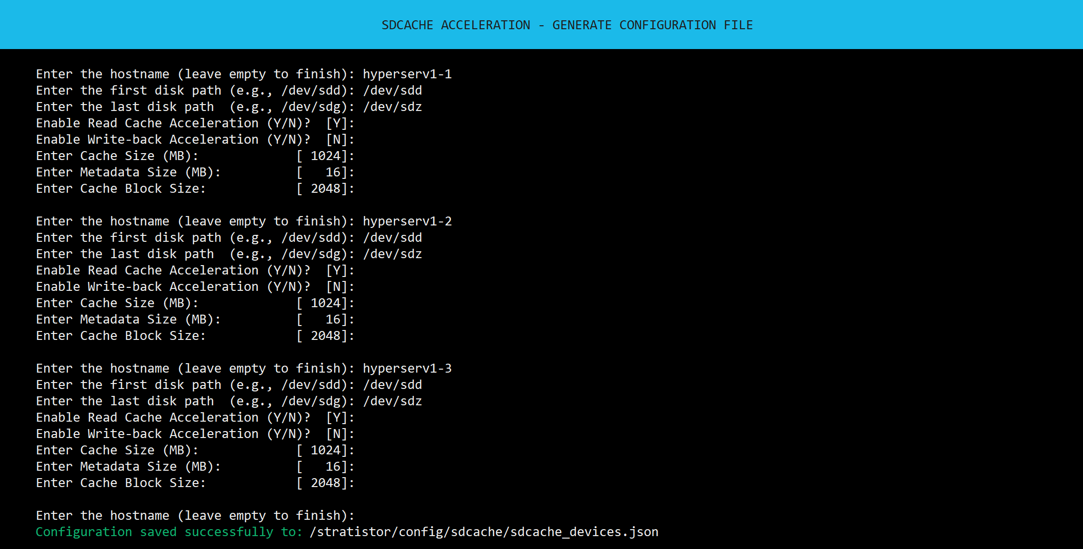
The command will ask for the following information:
- The hostname in the cluster containing the disks to be SDCache accelerated
- The first disk path in the sequence to activate
- The last disk path in the sequence to activate
- Whether to enable read-cache acceleration
- Whether to enable write-cache acceleration
- Individual cache size per disk
- Individual metadata size per disk (typically left unchanged)
- Individual cache block size per disk (typically left unchanged)
The operator will perform this for each of the nodes in the cluster. When complete, simply leave the hostname field blank to save the configuration file. The configuration will be written to:
/stratistor/config/sdcache/sdcache_devices.json
¶ SDCACHE CONFIGURATION FILE
The SDCache configuration file is used for a one-shot activation of SDCache on any number of backing devices across any number of nodes within the cluster. The file consists of the following structure:
{
  "NodeConfig": [
    {
      "Name": "stratistor1-1",
      "CacheConfig": {
        "Devices": [
          {
            "DevicePath": "/dev/sdb",
            "EnableCacheAcceleration": true,
            "EnableWritebackAcceleration": false,
            "CacheSizeMBs": 1024,
            "MetadataSizeMBs": 16,
            "CacheBlockSize": 2048
          },
          {
            "DevicePath": "/dev/sdc",
            "EnableCacheAcceleration": true,
            "EnableWritebackAcceleration": false,
            "CacheSizeMBs": 1024,
            "MetadataSizeMBs": 16,
            "CacheBlockSize": 2048
          }
        ]
      }
    },
    {
      "Name": "stratistor1-2",
      "CacheConfig": {
        "Devices": [
          {
            "DevicePath": "/dev/sdb",
            "EnableCacheAcceleration": true,
            "EnableWritebackAcceleration": false,
            "CacheSizeMBs": 1024,
            "MetadataSizeMBs": 16,
            "CacheBlockSize": 2048
          },
          {
            "DevicePath": "/dev/sdc",
            "EnableCacheAcceleration": true,
            "EnableWritebackAcceleration": false,
            "CacheSizeMBs": 1024,
            "MetadataSizeMBs": 16,
            "CacheBlockSize": 2048
          }
        ]
      }
    }
  ]
}SDCache has two primary purposes:
- Provide read and/or write RAM cache acceleration for all backing disks SDCache is configured with.
- Provide a compatibility layer for any disk type including complex backend storage arrays and multipath devices to be used with the cluster.
When using multipath disk devices, ensure that multipath is functioning correctly with the attached devices using the following command:
multipath -llIf modifications to the multipath configuration is required for any reason, the configuration can be found at:
/etc/multipath.conf¶ STRATISERV KUBERNETES INFRASTRUCTURE
When Kubernetes services are enabled, StratiSERV provides the compute foundation for containerized applications and HyperSERV can provide co-resident compute and StratiSTOR-backed persistent storage. Plan control-plane and worker roles, API access, cluster DNS, pod and service address ranges, ingress, load-balancer addresses, and persistent storage before deploying production workloads.
A basic advanced validation workflow is shown below. Exact component versions and supported storage classes are release-specific.
kubectl get nodes -o wide
kubectl get pods -A
kubectl get storageclass
kubectl get pvc -A
kubectl get events -A --sort-by=.lastTimestamp | tail -100- Verify all expected control-plane and worker nodes are Ready before deploying platform services.
- Use a supported StratiSTOR-backed storage class for persistent application data and document its access mode, reclaim policy, and protection behavior.
- Validate persistent data across pod rescheduling and node maintenance before placing a stateful application into production.
- Back up application data separately from Kubernetes configuration and control-plane state.
¶ OPENSTACK PRIVATE CLOUD SERVICES
OpenStack can be deployed as an optional private-cloud layer on StratiSYSTEM OS. StratiSERV supplies the compute foundation and StratiSTOR supplies supported persistent storage services. HyperSERV can host both layers in a converged design when the deployment has sufficient reserved CPU, memory, storage, and network capacity.
OpenStack is deployed on the StratiSERV Kubernetes foundation using the release-qualified deployment tooling supplied with the installed StratiSYSTEM OS build. StratiSYSTEM OS 4.9 environments using the Gazpacho deployment profile use an OpenStack-Helm based architecture. Do not assume that endpoint addresses, component versions, or deployment duration from an older release remain valid.
¶ Pre-deployment Requirements
- Healthy StratiSERV Kubernetes control-plane nodes and working cluster DNS.
- Defined management/LAN, tunnel/overlay, and external/provider network interfaces.
- An external bridge/provider-network design appropriate for the site.
- A supported StratiSTOR-backed Kubernetes storage class for OpenStack stateful services.
- Reserved load-balancer addresses, DNS names, and certificates for the intended API and Horizon endpoints.
- StratiSERV VM services enabled and validated before OpenStack compute services are activated.
¶ Post-deployment Validation
kubectl -n openstack get pods -o wide
kubectl -n openstack get svc
kubectl -n openstack get ingress
kubectl -n openstack get events --sort-by=.lastTimestamp | tail -100Before exposing the cloud to tenants, validate identity access, image upload, instance launch, tenant networking, external connectivity, persistent-volume attachment, instance deletion, and resource accounting. Use the endpoint displayed by the deployed service rather than relying on a hard-coded port from an older release.
The OpenStack API reference guide can be found here: OpenStack API Reference Guide
¶ ISCSI BLOCK SERVICES
iSCSI block services can be automatically deployed through the StratiSTOR provisioning engine. Upon selection, the engine first verifies that the cluster is in a valid state to enable iSCSI services. Once validated, deployment proceeds using the configuration defined in the service definition file.
It may be necessary to modify the service definition configuration. This can be done by modifying the iSCSI service definition file located at:
/stratistor/config/iscsi/stratistor_iscsi-service.yaml
Below is an example of the iSCSI service definition file:
service_type: iscsi
service_id: service-01
placement:
 count: 3
spec:
 pool: iscsi01.data
 api_user: superuser
 api_password: REPLACE_WITH_STRONG_PASSWORD
 api_port: 5000
 api_secure: true
 ssl_cert: |
    -----BEGIN CERTIFICATE-----
    ...
    -----END CERTIFICATE-----
 ssl_key: |
    -----BEGIN PRIVATE KEY-----
    ...
-----END PRIVATE KEY-----¶ Field Descriptions
service_type:Specifies the kind of service being deployed. In this case, the service is for managing block-based storage over a network using a standard protocol. For iSCSI, ensure this value remains set to:iscsiservice_id:A unique identifier for this service instance. It helps distinguish this particular deployment from other services of the same type.placement:count:Indicates the number of service instances or pods to deploy. For example, a count of3would deploy the service across three nodes or containers for redundancy or scalability.
spec:pool:Refers to the underlying storage group or namespace where block volumes will be provisioned from. The prefix of this value (i.e., iscsi01), must match the iSCSI pool name in the cluster current deployment file located at:/stratistor/config/deployment/current_deployment.json, at the value:IScsiPoolNameapi_user:Username used to authenticate with the service's management interface or API.api_password:The password associated with theapi_user. This is used for secure access to the service management functions.api_port:The TCP port on which the service’s API will listen. This is used for communication between clients or controllers and the service itself. Generally, this port does not need to be modified unless it conflicts with another service running at port 5000.api_secure:A boolean flag that indicates whether the API should use HTTPS (true) or plain HTTP (false). When set totrue, the service requires TLS encryption for API access.ssl_cert:The public certificate used to enable encrypted API communication. It ensures that clients can establish a secure connection and verify the identity of the service.ssl_key:The corresponding private key to the certificate. It is used by the service to establish secure, encrypted sessions with clients that connect to the API.
NOTE: Either a third-party certificate authority or self-signed certificate can be used with this configuration file. To generate a self-signed certificate, simply issue the following command at the terminal (adjust values as necessary):
openssl req -x509 -nodes -days 365 -subj "/C=US/ST=NY/L=New York/O=Acme Corp/OU=Engineering/CN=acmecorp.org" \
-newkey rsa:2048 -sha256 -keyout iscsi_key.pem -out iscsi_cert.pem \
-extensions v3_ca -addext "subjectAltName=DNS:acmecorp.org"Once the command is executed it will generate the PEM certificate and key files. Simply replace the respective values in the service definition file with the values in the PEM certificate files.
When the service definition file has been completely updated with the desired values, proceed to deploy the service based on these values using the StratiSTOR provisioning engine. Additional cluster-wide configuration changes can be made in the Storage Administration console located at https://[ANY NODE]:8443
¶ NVME BLOCK SERVICES
NVMe-oF block services can be automatically deployed through the StratiSTOR provisioning engine menu. Upon selection, the engine first verifies that the cluster is in a valid state to enable NVMe-oF services. Once validated, deployment proceeds using the configuration defined in the service definition file.
It may be necessary to modify the service definition configuration. This can be done by editing the NVMe-oF service definition file located at:
/stratistor/config/nvmeof/stratistor_nvmeof-service.yaml
Below is an example of the NVMe-oF service definition file:
service_type: nvmeof
service_id: service-01
placement:
 count: 3
spec:
pool: nvme01.data¶ Field Descriptions
service_type:Specifies the kind of service being deployed. For NVMe-oF, ensure this value is set to:nvmeof.service_id:A unique identifier for this service instance.placement:count:The number of service instances to run concurrently. A value of3typically provides high availability.
spec:Contains configuration parameters specific to this deployment.pool:Refers to the underlying storage pool from which block volumes will be provisioned. The prefix of this value (e.g.,nvme01) must match the NVMe-oF pool name defined in the cluster deployment file at:/stratistor/config/deployment/current_deployment.jsonunder the value:NvmeofPoolName.
When the service definition file has been completely updated with the desired values, proceed to deploy the service based on these values using the StratiSTOR provisioning engine. Additional cluster-wide configuration changes can be made in the Storage Administration console located at https://[ANY NODE]:8443
¶ STRATISTOR FIBRE CHANNEL GATEWAY
Release-specific capability: Where Fibre Channel gateway services are enabled in the installed StratiSYSTEM OS build, selected StratiSTOR block volumes can be presented to supported Fibre Channel initiators through one or more gateway nodes.
- Present the same logical volume identity consistently through every intended gateway path.
- Configure initiator-side multipathing so all supported target paths are discovered and managed as a single logical device.
- Validate path loss and recovery before production use. Path visibility alone does not establish active/active write semantics.
- Workloads requiring shared-disk coordination or persistent reservations must use a specifically supported locking and reservation design.
- Document target WWPNs, zoning, initiator access controls, LUN mapping, path policy, and the gateway failure procedure.
Only publish exact adapter, firmware, reservation, and gateway-count requirements after they are validated for the applicable StratiSYSTEM OS release.
¶ S3 OBJECT SERVICES (TERMINAL)
S3 object services can be deployed automatically using the StratiSTOR provisioning engine. Upon selection, the engine will check if the cluster is in a valid state to enable S3 services. Once verified, it will proceed with deployment using the selected configuration file.
There are two supported deployment modes - direct and load-balanced:
¶ 1. Direct S3 Deployment (No Front-end Load Balancer - No Ingress Service)
This mode directly exposes the S3 service on the specified port of the hosting node. SSL termination is handled by the S3 service itself.
Edit the service definition file located at:
/stratistor/config/s3/stratistor_s3-service-noingress.yaml
Example service definition for no-ingress:
service_type: rgw
service_id: steeldome.us-east-1
placement:
 count: 1
spec:
 rgw_frontend_type: beast
 rgw_realm: steeldome
 rgw_zone: us-east-1
 rgw_zonegroup: us
 rgw_frontend_port: 15443
 rgw_frontend_ssl_certificate: |
   -----BEGIN PRIVATE KEY-----
   ...
   -----END PRIVATE KEY-----
   -----BEGIN CERTIFICATE-----
   ...
   -----END CERTIFICATE-----
 ssl: true
¶ 2. Load-Balanced S3 Deployment (With Load Balanced Ingress Service)
This mode uses an ingress service to front multiple S3 gateways behind a single virtual IP and TLS endpoint. Ideal for high availability and consistent endpoint exposure.
Edit the two service definition files:
- Gateway Service:
/stratistor/config/s3/stratistor_s3-service.yaml - Ingress Service:
/stratistor/config/s3/stratistor_s3-service-ingress.yaml
Example Gateway Configuration:
service_type: rgw
service_id: steeldome.us-east-1
placement:
 count: 3
spec:
 rgw_frontend_port: 1111
 rgw_frontend_type: beast
 rgw_realm: steeldome
 rgw_zone: us-east-1
rgw_zonegroup: usExample Ingress Configuration:
service_type: ingress
service_id: rgw.steeldome.us-east-1
placement:
 count: 3
spec:
 backend_service: rgw.steeldome.us-east-1
 frontend_port: 15443
 monitor_port: 1112
 virtual_ip: 192.168.59.100/24
 ssl: true
 ssl_cert: |
   -----BEGIN CERTIFICATE-----
   ...
   -----END CERTIFICATE-----
   -----BEGIN PRIVATE KEY-----
   ...
-----END PRIVATE KEY-----¶ Field Descriptions
service_type:Defines the role of the service. Usergwfor the S3 gateway andingressfor load balancing.service_id:Unique identifier for the service. For HA deployments, the ingress and backend gateway IDs must be coordinated.placement.count:Number of instances to run. Use1for simple setups, or3for HA.rgw_frontend_type:Set tobeastto use the modern high-performance frontend.rgw_frontend_port:The port the gateway listens on. Typically15443for direct access or1111when ingress handles TLS.rgw_frontend_ssl_certificate:Required only for non-ingress deployments. Combines both private key and certificate for internal SSL termination.ssl:Boolean flag to enable TLS. Used in ingress configurations.ssl_cert:The TLS certificate and key for the ingress service. Not needed in direct (non-ingress) deployments.virtual_ip:The virtual IP address used by the ingress service for external exposure.backend_service:Refers to the gateway service being load balanced by the ingress.rgw_realm,rgw_zone,rgw_zonegroup:These must match the values defined in your deployment file at:/stratistor/config/deployment/current_deployment.json"S3Realm"→rgw_realm"S3Zone"→rgw_zone"S3ZoneGroup"→rgw_zonegroup
When the service definition file has been completely updated with the desired values, proceed to deploy the service based on these values using the StratiSTOR provisioning engine. Additional S3 configuration changes (i.e., bucket, user, and access key creation) can be made in the Storage Administration console located at https://[ANY NODE]:8443.
¶ S3 OBJECT SERVICES (WEB GUI)
S3 object services can be deployed manually via the web-based Storage Administration console located at https://[ANY NODE]:8443.
¶ Creating the S3 Service
The first step in configuring S3 services is to create the S3 service definition. From the menu on the left open Administration and select Services. The cluster services panel will populate with all the currently configured services in the cluster.
Next, click on the Create button to open the Create Service modal.
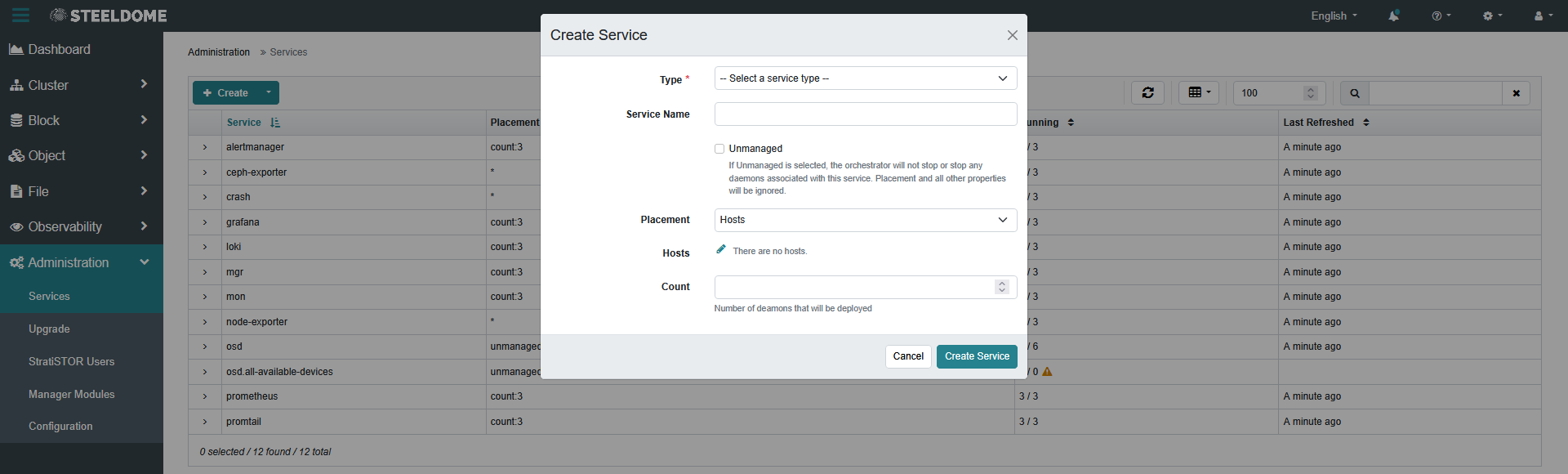
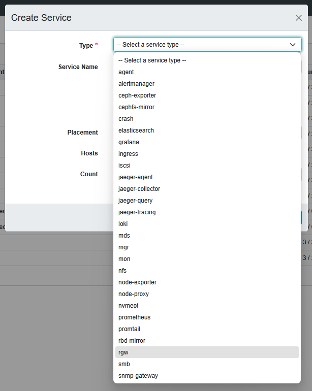
In the Type drop-down menu, select the RGW service (the StratiSTOR S3 gateway).
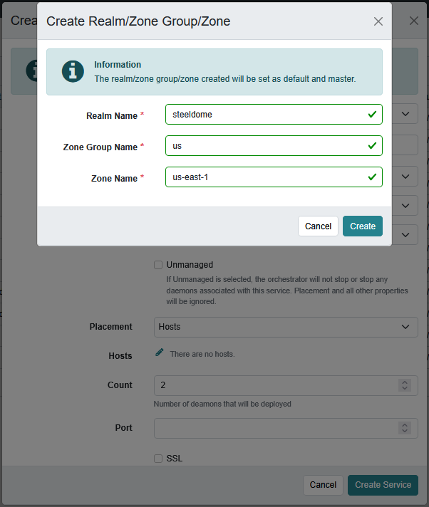
We must first define the S3 Realm, zone group and zone parameters. To do this, click on the Click Here link in the information panel.
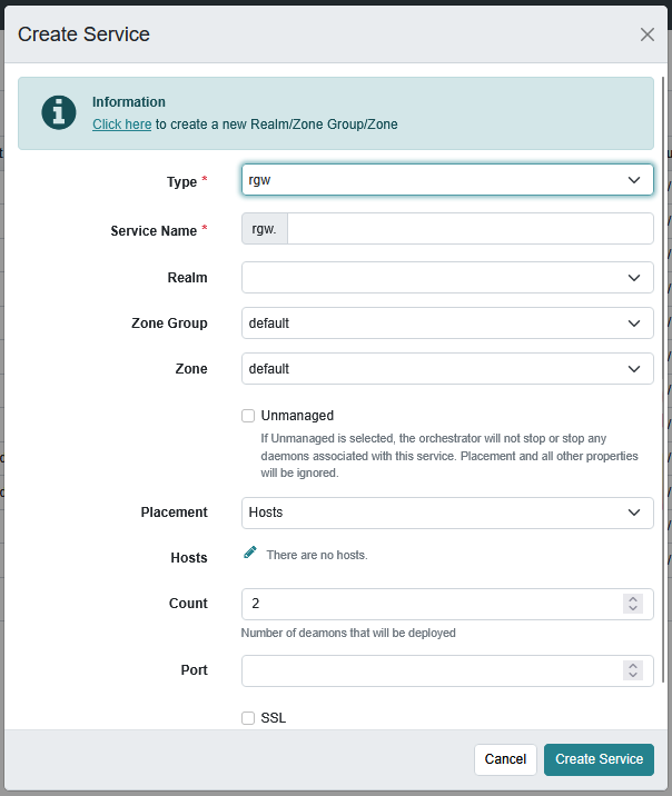
The Create Realm modal will open and prompt you to provide the Realm Name, Zone Group Name, and Zone Name. Fill these values in as appropriate. Remember these values as you will need them later on in the configuration process.
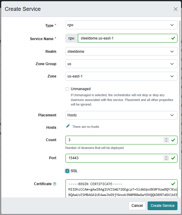
The next step is to provide the placement rule, count and port number to advertise the S3 services on. In a normal cluster configuration of 3 or more hosts, the placement value should be set to Hosts and the count set to the number of hosts in the cluster (or the number you wish to advertise S3 service from). The port number should be any port that is not currently in use within the cluster.
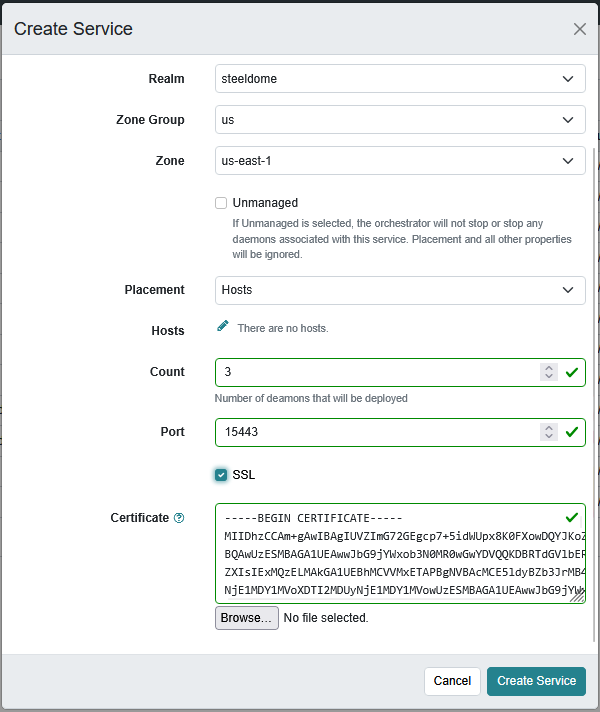
Next, it is highly recommended to enable SSL communication. This will require you to provide a full PEM certificate (one containing both the certificate and private key chains). This should be either copy/pasted into the Certificate textbox or provided via an uploaded file using the Browse button.
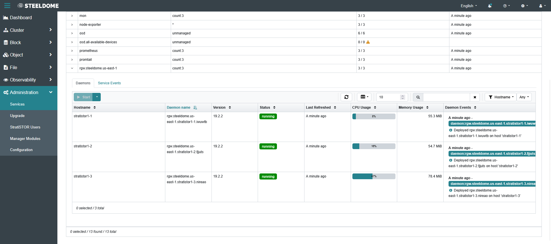
Once the service has been deployed within the cluster, you will see the rgw service appear. If you expand the service drop-down you will also see the service state on each host.
The service deployment will also create a set of storage pools to support the S3 services.
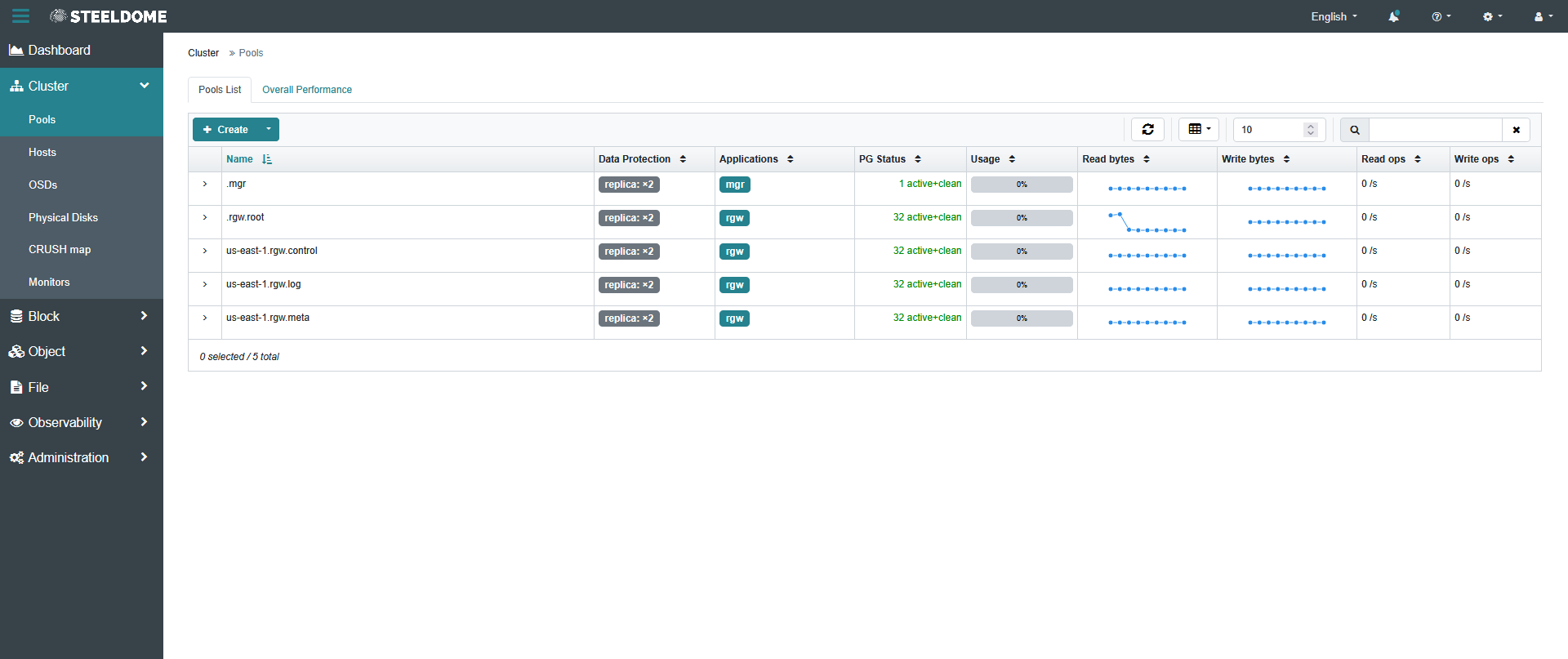
The next step is to enable the management module which will expose the administration consoles for the S3 service in the Web GUI. Under Administration, click on Manager Modules. Look for the module named rgw.
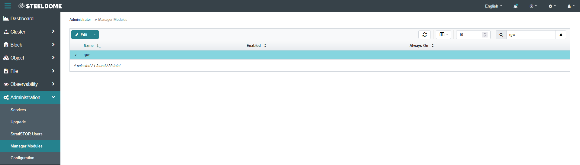
Highlight the rgw module and in the drop-down menu, select Enable.

NOTE: Do not disable TLS certificate verification to make a self-signed S3 certificate work. For production environments, use a certificate issued by a trusted internal or public certificate authority. If an internal CA is used, install the CA certificate in the StratiSYSTEM OS trust store and in the administrator's client trust store.
# Example: trust an internal CA certificate on the StratiSYSTEM OS node
cp /path/to/organization-root-ca.crt /etc/pki/ca-trust/source/anchors/stratistor-s3-ca.crt
update-ca-trustAfter the trust chain is installed, verify that the S3 endpoint certificate name matches the DNS name used by the Storage Administration console and that the complete certificate chain is presented. Keep certificate verification enabled.
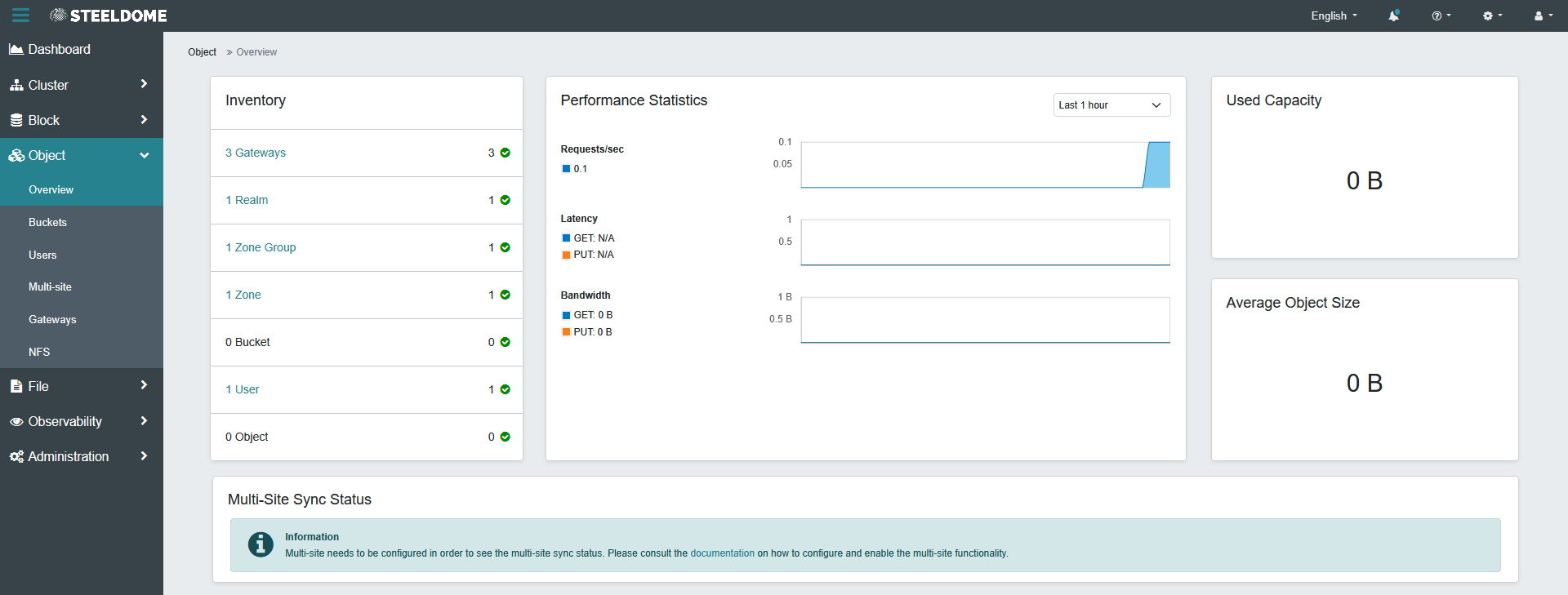
Once the module is enabled, allow for up to 60 seconds for the module to become active. Once active, proceed to the Object section of the menu and click on Overview. This will provide a high-level status of the S3 services in the cluster.
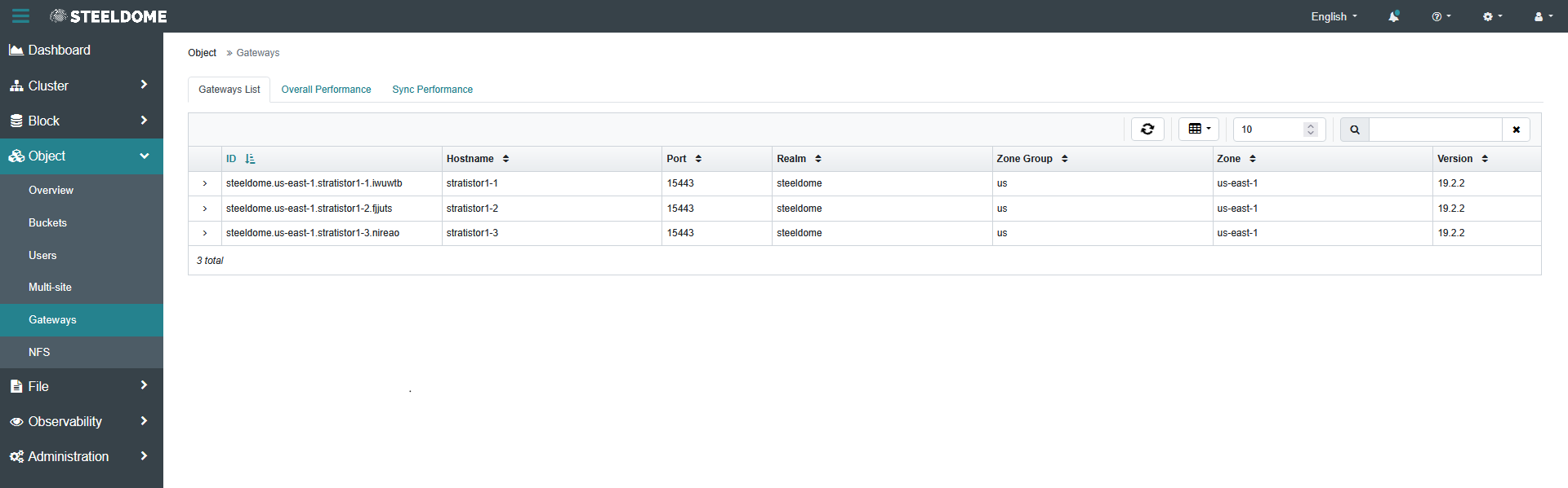
Click on Gateways to see a manifest of all gateway services available in the cluster. This should match the count number you provided during the Create Service phase earlier in this process.
¶ Configuring the S3 Service
Now that the S3 service has been deployed and is operational, the final phase is to create users and buckets. To begin, under Object, click on Users. This will display the current S3 users provisioned in the cluster. Click on the Create button to open the Create User wizard.
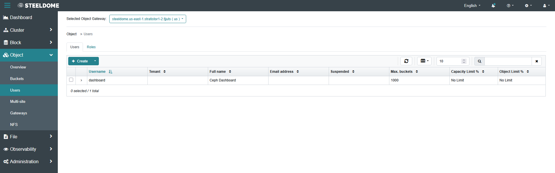
Proceed with providing valid input values for the User ID, tenant (optional), Full Name, and Email Address fields. By default, an S3 key/secret pair will auto-generated. Optionally, you can override the S3 key/secret values, and enable user and bucket quotas. When completed, simply click on the Create button to create the user.
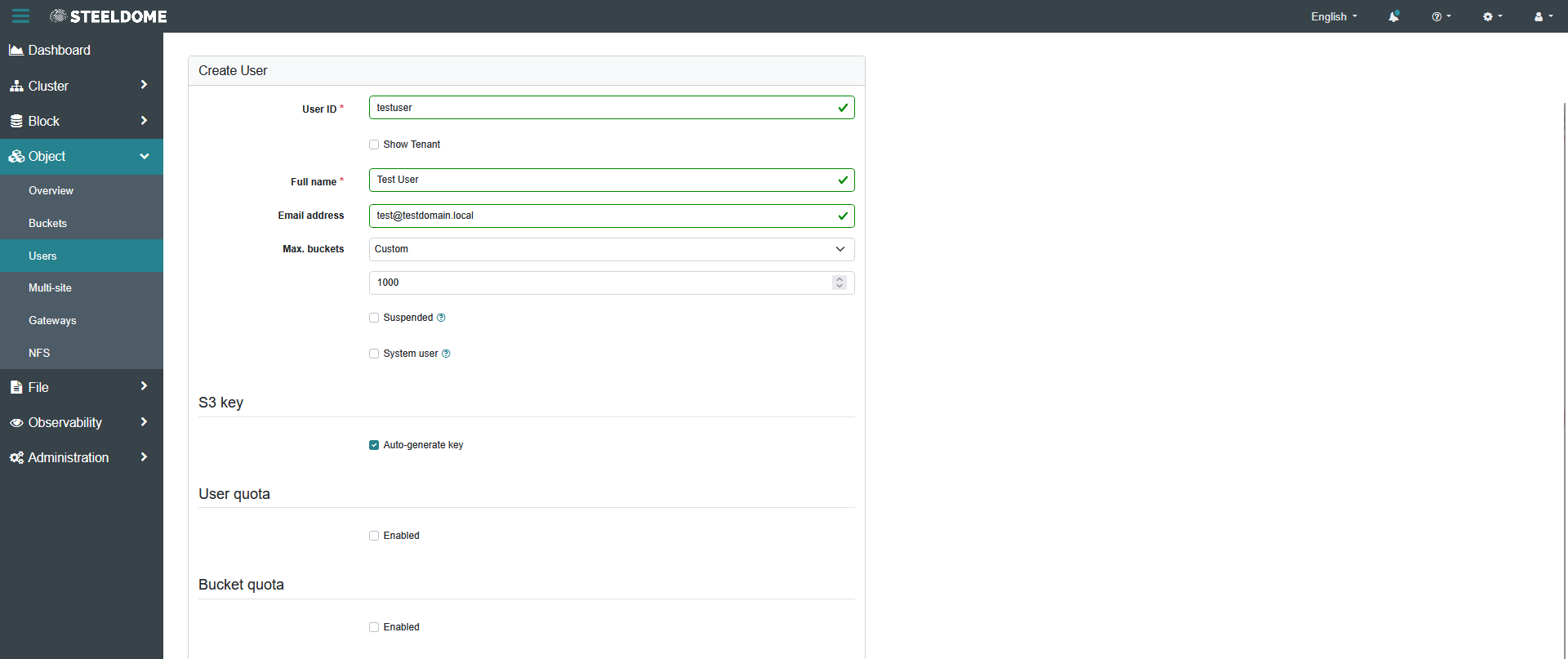
The new user will now appear in the Users table. If you auto-generated the S3 key/secret, you can select the User in the table and click on the Show button to see the assigned key and secret values. These values will be used to access the buckets for which the user has access.
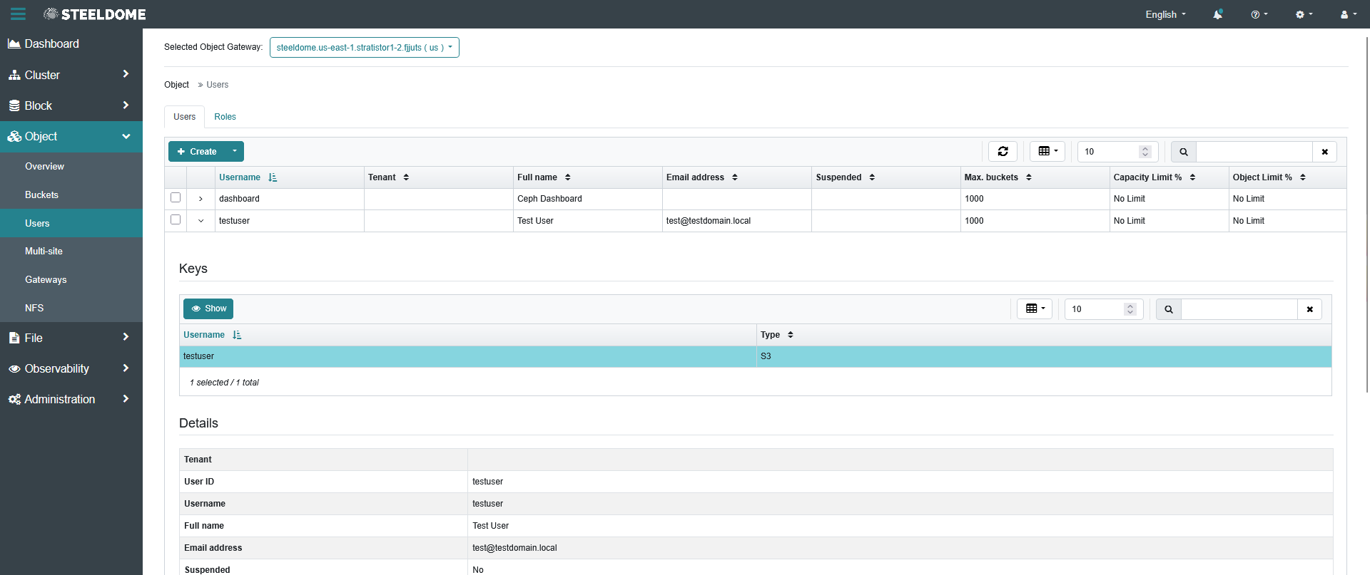
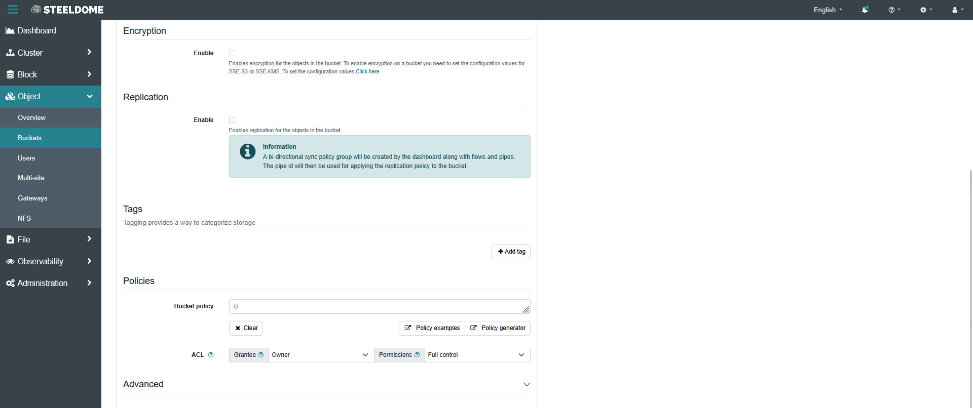
Now that a user has been defined, under Object, click on Buckets. This will display the current S3 buckets provisioned in the cluster. Click on the Create button to open the Create Bucket wizard. Enter a valid name for the bucket and assign a default owner from the Owner drop-down. You should see at least one user which was created in the previous step. Optionally, you can enable features such as Object Locking, Encryption, and Replication.
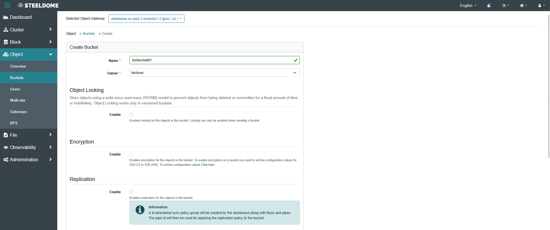
Policies can also be defined in accordance with AWS policy rules. If unsure or unnecessary at this phase, simply scroll down and complete the bucket creation process by clicking on the Create button to create the bucket.
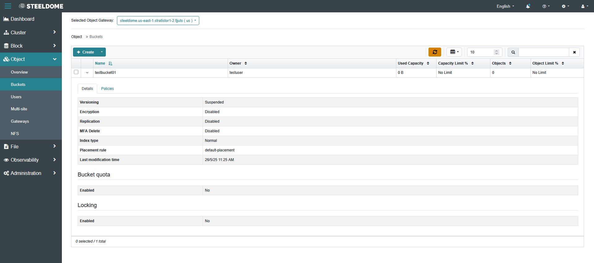
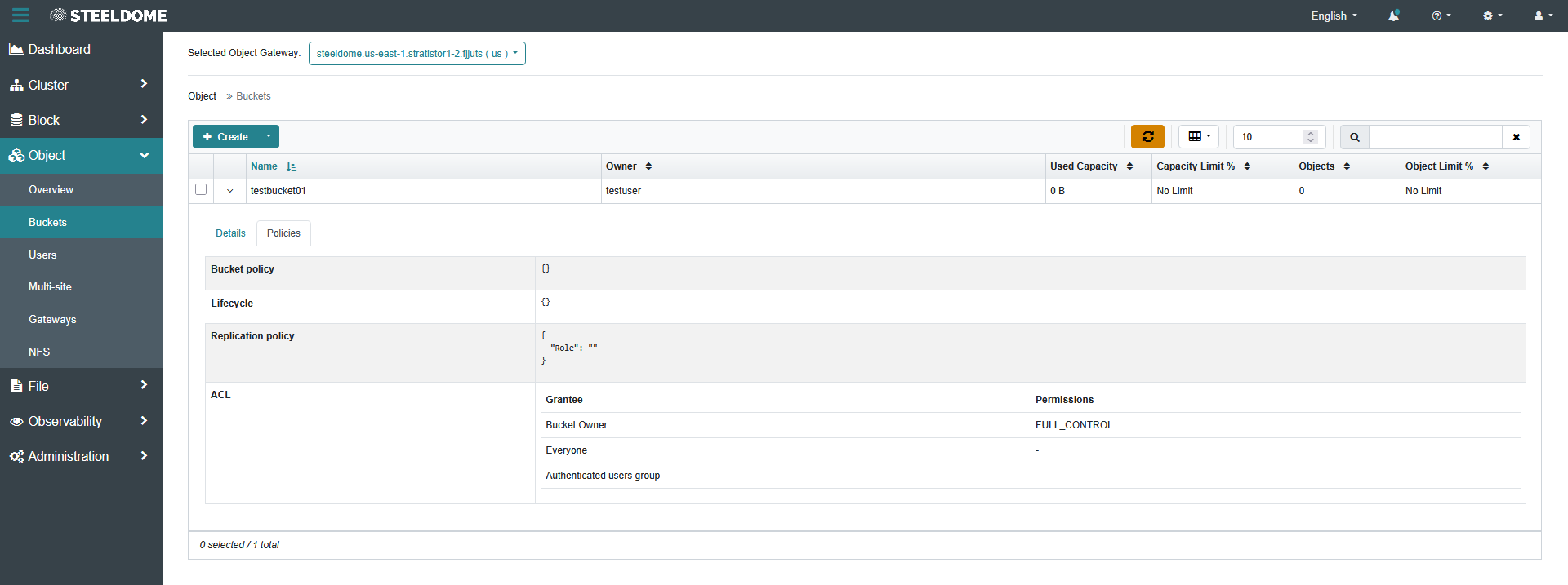
Now that the bucket has been created, it will appear in the bucket table displaying all provisioned buckets in the cluster. The bucket details and assigned policies are also available from this view as shown below.
¶ Configuring the S3 Multi-Site Service
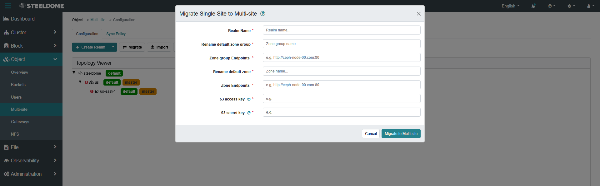
S3 services can operate across multiple sites to provide distribution and redundancy for the S3 data. To access the Multi-site configuration screen, click on Object in the menu and then Multi-Site.
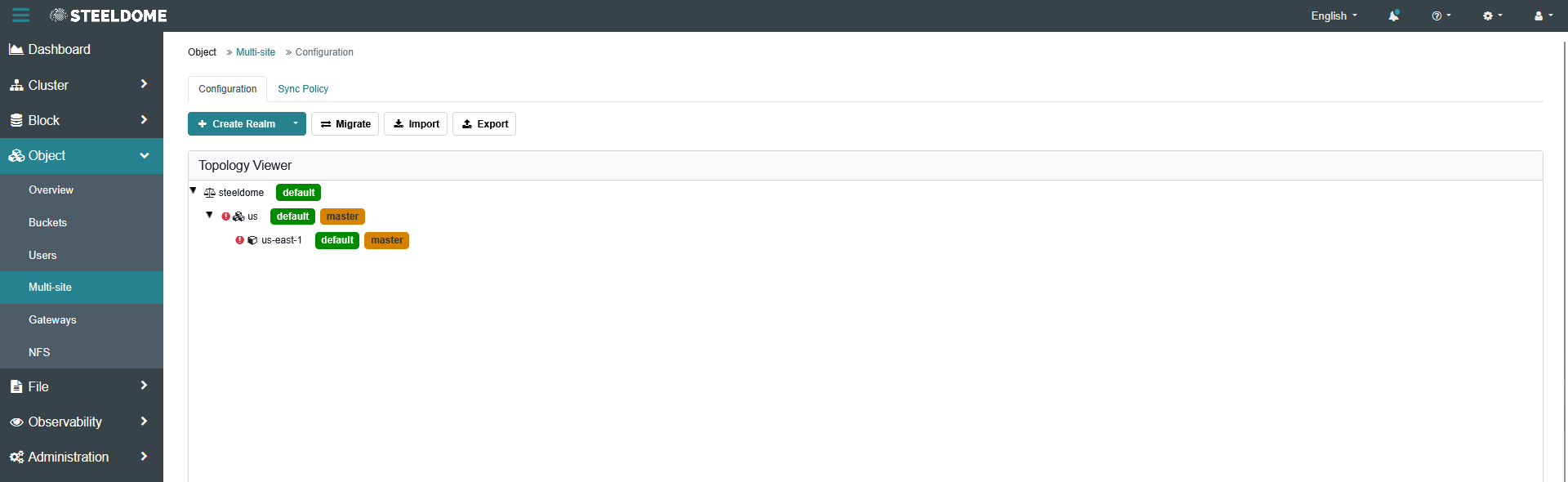
There are several wizards available to configure the Multi-Site capabilities depending on what needs to be done in a multi-site scenario.
¶ SMB FILE SERVICES
SMB file services can be deployed automatically using the StratiSTOR provisioning engine. Upon selection, the engine will check if the cluster is in a valid state to enable SMB file services. Once verified, it will proceed with deployment using the selected configuration file.
It may be necessary to modify the deployment configuration to adjust specific SMB settings. This can be done by editing the deployment configuration file located at:
/stratistor/config/deployment/current_deployment.json
Since SMB is a clustered HA service, a VIP (virtual IP) is used to advertise the SMB services across the entire cluster. The VIP can be changed by modifying the following parameter in the deployment configuration file:
clusterConfig:SmbServicesVip:Available IP address (on any interface common to all cluster nodes) defined in full CIDR format, for example:192.168.1.100/24
When the deployment configuration file has been completely updated with the desired values, proceed to deploy the service based on these values using the StratiSTOR provisioning engine. Additional cluster-wide configuration changes can be made in the Storage Administration console located at https://[ANY NODE]:8443
¶ High-Performance SMB and Multichannel
Where the selected StratiSTOR file-service mode and client operating system support SMB Multichannel, multiple network paths can be used by a single SMB session. The achievable aggregate throughput is determined by the physical adapters, client/server implementation, routing, storage backend, CPU/NUMA locality, and workload. Assigning multiple IP addresses to one physical adapter does not increase that adapter's physical bandwidth.
- For multi-NIC designs, verify that each intended physical adapter is operational at the expected link speed and has a valid client-to-server path.
- Keep MTU, routing, and firewall policy consistent across every path used for the SMB session.
- During performance testing, measure traffic on the physical interfaces in addition to the SMB application rate.
- Validate failover by removing one path and confirming the workload continues on the remaining supported path or paths.
# Linux / StratiSYSTEM network validation
ip -br link
ip -s link
ethtool <interface>
ss -tin

# Linux SMB client channel information, when supported
cat /proc/fs/cifs/DebugData 2>/dev/null

# Windows client
Get-SmbMultichannelConnection

# macOS client
smbutil multichannel -a¶ NFS FILE SERVICES
NFS file services can be deployed automatically using the StratiSTOR provisioning engine menu. Upon selection, the engine checks if the cluster is in a valid state to enable NFS services. Once validated, deployment proceeds using the selected configuration file.
There are two supported deployment modes for NFS:
¶ 1. Direct NFS Deployment (No Front-end Load Balancer - No Ingress Service)
This method directly exposes NFS services on the hosting node's NFS port (2049). It is recommended for basic setups or environments where a load balancer is not needed.
Edit the service definition file located at: /stratistor/config/nfs/stratistor_nfs-service.yaml
Ensure the port is set to 2049 for direct access:
Example Direct Access Configuration:
service_type: nfs
service_id: steeldome.us-east-1
placement:
 count: 3
spec:
 port: 2049
¶ 2. Load-Balanced NFS Deployment (With Load Balanced Ingress Service)
This mode uses an ingress service to front the NFS gateway behind a single virtual IP. This is ideal for high availability, automatic failover, and a consistent external endpoint.
Edit the two service definition files:
- Gateway Service:
/stratistor/config/nfs/stratistor_nfs-service.yaml(Setportto a non-standard internal port, e.g.,2222) - Ingress Service:
/stratistor/config/nfs/stratistor_nfs-ingress.yaml
Example Gateway Configuration (for Ingress use):
service_type: nfs
service_id: steeldome.us-east-1
placement:
 count: 3
spec:
port: 2222Example Ingress Configuration:
service_type: ingress
service_id: nfs.steeldome.us-east-1
placement:
 count: 3
spec:
 backend_service: nfs.steeldome.us-east-1
 frontend_port: 2049
 monitor_port: 2223
virtual_ip: 192.168.59.100/24¶ Field Descriptions
service_type:Defines the type of service being deployed. Useingressfor the load balancer.service_id:Unique identifier for the service instance. The ingress and backend service IDs must match accordingly.placement:count:Number of instances to deploy. Use3for HA or1for minimal setups.
port:The TCP port on which the NFS gateway listens. Use2049for direct deployments (standard NFS port). Use an internal port like2222if behind an ingress.spec:backend_service:The ID of the NFS service the ingress will forward traffic to.frontend_port:The external port clients will use to access the NFS service. Typically2049.monitor_port:The port used internally by the ingress to monitor backend service health.virtual_ip:The floating IP address used by the ingress to expose the service.
¶ Cluster Deployment Reference
The NFS configuration must align with values in the deployment descriptor located at: /stratistor/config/deployment/current_deployment.json
Example Deployment Configuration:
"EnableNfsHaServices": false,
"NfsServicesFileSystemVolumeName": "nfs01",
"NfsClusterId": "steeldome.us-east-1",
"NfsPseudoPath": "nfs01"These values should match:
NfsClusterId→service_idNfsServicesFileSystemVolumeName→ underlying filesystem volume usedNfsPseudoPath→ the exported pseudo path in the NFS share
When the deployment configuration file has been completely updated with the desired values, proceed to deploy the service based on these values using the StratiSTOR provisioning engine. Additional cluster-wide configuration changes can be made in the Storage Administration console located at https://[ANY NODE]:8443
¶ NFS Client Validation
After creating the NFS service and export, validate name resolution, reachability, export visibility, mount behavior, read/write permissions, and failover from a representative client.
# Examples - substitute the deployed VIP/endpoint and pseudo path
getent hosts <NFS-ENDPOINT>
showmount -e <NFS-ENDPOINT> 2>/dev/null || true
mkdir -p /mnt/stratistor-nfs-test
mount -t nfs4 <NFS-ENDPOINT>:/<PSEUDO-PATH> /mnt/stratistor-nfs-test
mount | grep stratistor-nfs-test¶ STRATISTOR DATA REDUCTION — COMPRESSION, DEDUPLICATION AND BLOCK SHARING
StratiSTOR provides three complementary approaches to reducing physical storage consumption: inline compression encodes eligible data using fewer bytes, fast block deduplication identifies and references matching blocks within participating storage tiers, and copy-on-write block sharing preserves common physical blocks across snapshots, clones and supported file-copy operations. Each method operates at a different point in the data lifecycle, with its own sharing scope, metadata requirements and performance characteristics.
Mechanism | How it operates | Primary technical characteristic |
Inline compression |
Compresses eligible write records and expands them transparently when read. |
Preserves the logical data interface while lowering physical allocation and potentially the backend I/O volume. |
Fast deduplication |
Uses block fingerprints, lookup metadata and reference counts to reuse existing identical blocks. |
Consolidates duplicate content only inside the enabled deduplication tier and participating datasets. |
Copy-on-write sharing |
Allows snapshots, writable clones and compatible file copies to reference existing physical blocks. |
Allocates additional space only as shared blocks are modified or replaced. |
¶ Inline Compression and Sparse Allocation
StratiSTOR compresses eligible records during the write path and transparently decompresses them on read. Distributed storage pools support pool-level compression, while supported datasets provide further per-record compression capabilities. Applications continue using their normal block, file or object interfaces; the amount saved depends on the content, record layout, update pattern and available CPU resources.
- LZ4: Prioritizes low processing overhead and rapid decompression, making it suitable when throughput and latency matter more than the highest compression ratio.
- Zstandard (Zstd): Provides selectable compression levels and speed-focused modes so operators can balance CPU effort against stored size on supported datasets.
- Incompressible content: Records that would not benefit from encoding can be stored without compression rather than incurring ineffective expansion.
- Zero-filled regions: Sparse representations avoid allocating complete physical records for data that contains no meaningful payload.
¶ Fast Block Deduplication and Reference Tracking
Within a configured deduplication tier, StratiSTOR computes block fingerprints and consults the deduplication table before allocating another physical copy. When a matching entry is eligible for reuse, the new write can reference the existing block. Reference counts keep that block allocated for as long as any dataset still references it. Supported verification modes can compare matching content byte for byte to confirm that blocks are identical.
Fast deduplication uses compact table entries and batched metadata updates to limit random lookup and update I/O. A configurable quota bounds the growth of on-disk deduplication metadata; when that quota is reached, existing tracked references remain valid even if new entries cannot be admitted. Pruning can discard older single-reference entries that are not producing space savings. Redundant high-speed storage can host the deduplication metadata when the table exceeds the desired in-memory footprint.
Operating boundary | Technical behavior |
Sharing domain |
Identical blocks are shared only within participating datasets, pools and deduplication scopes; sharing is not automatically global across all StratiSTOR services, tenants or sites. |
Metadata overhead |
Fingerprint lookups, reference counts, table occupancy, caching and updates add measurable CPU, memory and I/O demand. |
Capacity-efficiency tier |
The deduplication tier is intended for capacity reduction and is not the intended storage tier for active VM datastores. Provision latency-sensitive virtual-machine storage on an appropriate StratiSTOR tier. |
¶ Copy-on-Write Snapshots, Clones and Block Cloning
A StratiSTOR snapshot preserves the references needed to reconstruct a point-in-time dataset. A writable clone initially shares those underlying blocks with its origin, and compatible block-cloning file operations can create new references without rereading and rewriting the complete payload. When shared content diverges, new physical blocks are allocated for the modified data. These savings do not require general-purpose deduplication.
Block sharing is subject to supported dataset boundaries, compatible block layouts and encryption-key constraints. A snapshot can continue holding older blocks even after files are modified or deleted in the active dataset, so logical deletion does not necessarily produce an immediate equivalent amount of free physical capacity.
¶ Record Geometry, Physical Allocation and Protection Overhead
Record size influences compression opportunities and metadata density. Larger records give the compression algorithm more content to analyze and spread metadata costs across more bytes; smaller records can align more closely with fine-grained random writes but may increase metadata counts and reduce compression savings. Select the appropriate geometry according to the actual I/O size, overwrite behavior and latency objectives rather than a universal setting.
Effective capacity must be calculated from the physical allocation after compression, deduplication and block sharing, and then account for replication or erasure coding, metadata, retained snapshots and operational free space. Since several mechanisms may share the same underlying blocks, their reported reductions cannot simply be added together without risking double-counting.
¶ Compressed and Incremental Replication
For supported datasets, snapshot-based incremental replication transfers only the changes between snapshots instead of copying a complete dataset again. Compatible sending and receiving systems can preserve stored compressed blocks during transmission, avoiding unnecessary decompression and recompression. Network savings depend on how much data changed, snapshot ancestry and supported features at both ends. Local deduplication savings do not automatically imply the same reduction in replication traffic.
¶ Compression, Encryption and Raw Replication
On supported encrypted datasets, StratiSTOR applies compression before storage-layer encryption so reducible plaintext can be compressed before it becomes ciphertext. Raw encrypted replication can preserve encrypted content on the receiving side without providing plaintext decryption keys to that destination. Deduplication of encrypted content has a narrower sharing boundary, including the encrypted dataset and its supported snapshots or clones.
Content encrypted by an application before being submitted to StratiSTOR generally contains little exploitable compressible structure or repeated plaintext. The effectiveness of reduction therefore differs between application-side ciphertext and data encrypted within the StratiSTOR storage layer.
¶ Recompression of Existing File Data
A supported file-rewrite facility can apply different compression settings to existing file blocks without changing their logical contents. Where logical block birth times are preserved, a physical recompression does not need to cause otherwise unchanged content to enter subsequent incremental replication streams as new logical data. Recompression does not change the existing logical record size.
Rewriting a block referenced by a snapshot or clone can increase physical consumption while the older encoded block remains referenced. Operators should validate available space, physical write volume and snapshot retention before undertaking large-scale recompression.
Metric | What operators should validate |
Logical and physical size |
Measure logical content against allocated physical storage after all reduction mechanisms, avoiding double-counting shared blocks. |
Deduplication metadata |
Review unique-block counts, table quota/occupancy and lookup/cache behavior rather than assuming a fixed memory-per-terabyte requirement. |
Protected usable capacity |
Include replication or erasure-coding overhead, retained snapshots, metadata and adequate recovery headroom. |
Service performance |
Validate peak write throughput, latency, metadata pressure and recovery behavior alongside the observed reduction ratio. |
OPERATOR NOTE: Compression and block sharing can be employed independently of the fast-deduplication tier. Storage reduction must be evaluated against the workload and protection design; a high reduction ratio alone does not establish that a tier is appropriate for a particular I/O workload.
¶ AI, GPU, AND HIGH-PERFORMANCE COMPUTING
StratiSYSTEM OS can combine StratiSERV compute, high-speed networking, StratiSTOR data services, and supported GPU technologies for AI training, inference, analytics, rendering, and HPC workloads. The complete hardware and software path must be validated for the installed release.
- Dedicated GPU assignment: Treat PCI/GPU passthrough as a placement constraint because the workload can run only on hosts with an eligible device assignment.
- Shared GPU: NVIDIA vGPU or AMD MxGPU requires a compatible GPU, firmware, host driver, guest driver, and any applicable vendor licensing.
- Container GPU access: Validate the Kubernetes device integration, runtime configuration, scheduling resources, and persistent-data path before production deployment.
- Accelerated I/O: GPUDirect, BlueField/DOCA, ROCm, and other acceleration technologies require a supported topology; the presence of a GPU or high-speed adapter alone does not establish an accelerated data path.
- HPC: Use Lustre where its parallel-file-system model fits the workload, and use StratiSTOR services where block, file, or object access and distributed protection are the better fit.
¶ LUSTRE PARALLEL FILE SYSTEM
The Lustre Parallel File System (PFS) is a high-performance, scalable storage solution designed for large-scale computing environments. Widely used in supercomputing and enterprise data centers, Lustre enables multiple clients to access data concurrently across a distributed architecture. By separating metadata and data operations and leveraging parallel I/O, it delivers exceptional throughput and is optimized for workloads that require fast, simultaneous access to massive datasets.
¶ NOTES
- When Lustre PFS is deployed within HyperSERV as VMs, this allows Lustre to co-exist simultaneously with StratiSTOR block, file, and object clustered storage services.
- If Lustre is being deployed on bare-metal, utilize the Lustre Prep Engine for the deployment.
- If Lustre is being deployed within HyperSERV, utilize the StratiSTOR Provisioning Engine for automated deployment within the cluster.
- Whether deploying on bare-metal or within VMs, the Lustre system that is provisioned contains all Lustre modules including ZFS, Cluster Shell, and Slurm.
The StratiSYSTEM OS supports deploying Lustre PFS in the following ways:
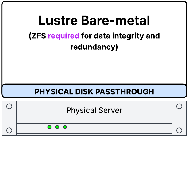 |
Deployed directly on bare-metal (ZFS required to be enabled) Lustre runs natively on physical servers with direct access to hardware, offering maximum performance and lowest latency. ZFS is required for data integrity, disk redundancy, and storage management on each node. In this mode, any combination of block devices can be utilized to form the logical devices which back the MGS, MGT, and OST roles within the cluster. Any supported RAID-Z level can be utilized based on the available disks and operational requirements for the cluster.
|
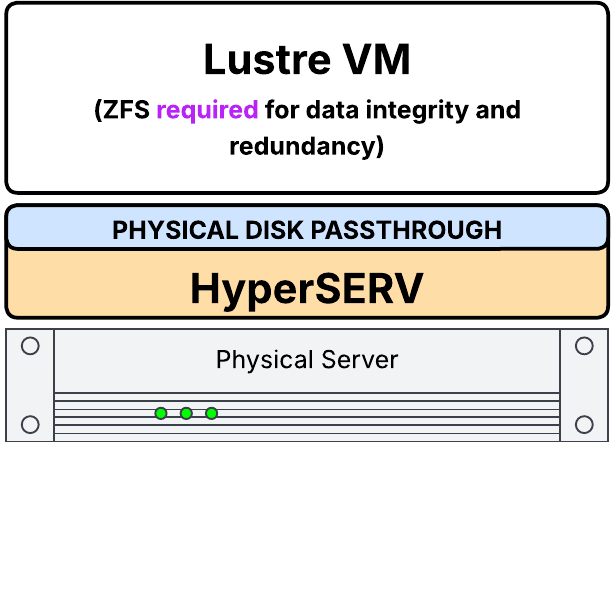 |
Deployed within HyperSERV as VMs with physical disk pass-through (ZFS required to be enabled) Lustre services run inside virtual machines across the HyperSERV cluster, with raw physical disks passed directly to each VM. ZFS is required for data integrity, disk redundancy, and storage management on each node. In this mode, any combination of block devices can be utilized to form the logical devices which back the MGS, MGT, and OST roles within the cluster. Any supported RAID-Z level can be utilized based on the available disks and operational requirements for the cluster. |
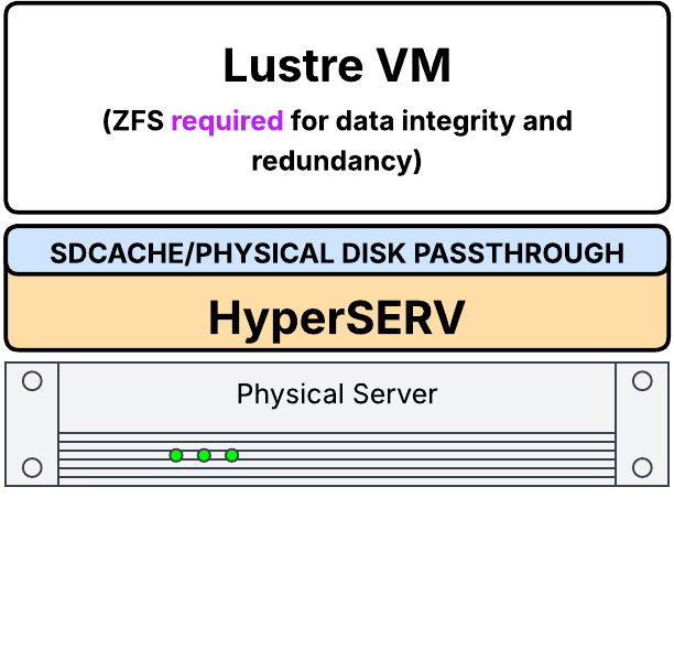 |
Deployed within HyperSERV as VMs with SDCache accelerated physical disk pass-through (ZFS required to be enabled) Similar to the previous setup, but with the addition of SDCache acceleration on the passthrough disks. ZFS is required for data integrity, disk redundancy, and storage management on each node. In this mode, any combination of block devices can be utilized to form the logical devices which back the MGS, MGT, and OST roles within the cluster. Any supported RAID-Z level can be utilized based on the available disks and operational requirements for the cluster. |
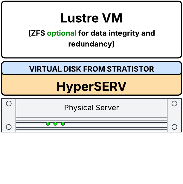 |
Deployed within HyperSERV as VMs with virtual disks residing on cluster storage (ZFS optional) Lustre is hosted in VMs with virtual disks backed by HyperSERV’s distributed storage. ZFS is optional as the underlying StratiSTOR layer provides the necessary data integrity and device redundancy. |
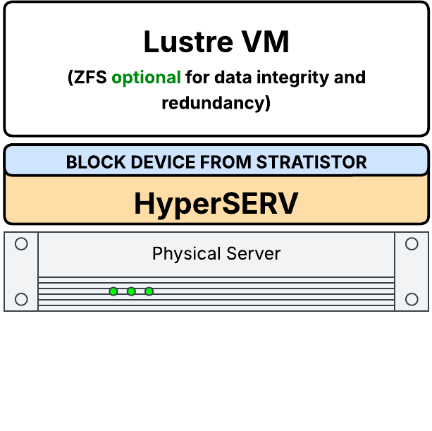 |
Deployed within HyperSERV as VMs distributed across cluster with block disks residing on cluster storage (ZFS optional) Lustre runs in VMs using block-based virtual disks provisioned from HyperSERV’s distributed block storage. ZFS is optional as the underlying StratiSTOR layer provides the necessary data integrity and device redundancy. |
¶ LUSTRE DEVICE SAFETY
WARNING: The Lustre formatting and ZFS pool-creation commands below are destructive. Never copy example device names directly into a production command. Identify the intended data devices by persistent path, verify that none is the StratiSYSTEM OS boot device, and confirm that the target devices contain no required data before proceeding.
lsblk -e7 -o NAME,PATH,SIZE,TYPE,FSTYPE,MOUNTPOINTS,MODEL,SERIAL,WWN
findmnt /
ls -l /dev/disk/by-id/ | less¶ CONFIGURATION OF LUSTRE FOR USE WITH SDCACHE ACCELERATED DISKS
Before activating Lustre on SDCache-accelerated disks, SDCache must first be enabled using the HyperSERV provisioning workflow. Physical devices should normally be assigned to the Lustre VM through the StratiSERV management interface. The following underlying StratiSERV CLI example is provided for advanced administrators who require command-line operation.
IMPORTANT: Replace every example source device with the persistent path of the intended SDCache device. Confirm the VM name and target device name before attaching a disk. Do not attach the StratiSYSTEM OS boot device.
# PfsNode-1, PfsNode-2, PfsNode-3 are the registered names for the Lustre VMs on each host.
# Replace the source paths below with the verified persistent paths for the SDCache accelerated disks.

# HYPERSERV NODE-1
virsh attach-disk PfsNode-1 /dev/disk/by-id/REPLACE-SDCACHE-DISK-1 vdb --persistent --targetbus virtio --type disk
virsh attach-disk PfsNode-1 /dev/disk/by-id/REPLACE-SDCACHE-DISK-2 vdc --persistent --targetbus virtio --type disk
virsh attach-disk PfsNode-1 /dev/disk/by-id/REPLACE-SDCACHE-DISK-3 vdd --persistent --targetbus virtio --type disk

# HYPERSERV NODE-2
virsh attach-disk PfsNode-2 /dev/disk/by-id/REPLACE-SDCACHE-DISK-1 vdb --persistent --targetbus virtio --type disk
virsh attach-disk PfsNode-2 /dev/disk/by-id/REPLACE-SDCACHE-DISK-2 vdc --persistent --targetbus virtio --type disk
virsh attach-disk PfsNode-2 /dev/disk/by-id/REPLACE-SDCACHE-DISK-3 vdd --persistent --targetbus virtio --type disk

# HYPERSERV NODE-3
virsh attach-disk PfsNode-3 /dev/disk/by-id/REPLACE-SDCACHE-DISK-1 vdb --persistent --targetbus virtio --type disk
virsh attach-disk PfsNode-3 /dev/disk/by-id/REPLACE-SDCACHE-DISK-2 vdc --persistent --targetbus virtio --type disk
virsh attach-disk PfsNode-3 /dev/disk/by-id/REPLACE-SDCACHE-DISK-3 vdd --persistent --targetbus virtio --type diskThe SDCache accelerated disks should now be visible from within the Lustre PFS VM on each HyperSERV node. If ZFS is required for these devices, please see the next section related to configuration of Lustre for use with ZFS.
¶ CONFIGURATION OF LUSTRE FOR USE WITH ZFS
The following example assumes three data devices are dedicated to each of three Lustre nodes. Replace every /dev/disk/by-id/REPLACE-... value with the verified persistent path for the intended data device. The example creates the ZFS pool first, then allows mkfs.lustre to create the Lustre dataset inside that pool.
NODE-1 ZFS Pool Provisioning (MGS/MDT)
# IP Address: 192.168.59.201
# DESTRUCTIVE: verify these are data devices and not the StratiSYSTEM OS disk.
D1=/dev/disk/by-id/REPLACE-NODE1-DISK1
D2=/dev/disk/by-id/REPLACE-NODE1-DISK2
D3=/dev/disk/by-id/REPLACE-NODE1-DISK3

lsblk -f "$D1" "$D2" "$D3"
zpool create -f -O canmount=off -o multihost=on -o cachefile=none mgsmdt raidz1 "$D1" "$D2" "$D3"
mkfs.lustre --reformat --fsname=lustrefs --mgs --mdt --backfstype=zfs --index=0 mgsmdt/mgsmdt
mkdir -p /lustre/lustrefs/mdt0
mount -t lustre mgsmdt/mgsmdt /lustre/lustrefs/mdt0NODE-2 ZFS Pool Provisioning (OST)
# IP Address: 192.168.59.202
D1=/dev/disk/by-id/REPLACE-NODE2-DISK1
D2=/dev/disk/by-id/REPLACE-NODE2-DISK2
D3=/dev/disk/by-id/REPLACE-NODE2-DISK3

lsblk -f "$D1" "$D2" "$D3"
zpool create -f -O canmount=off -o multihost=on -o cachefile=none ost0001 raidz1 "$D1" "$D2" "$D3"
mkfs.lustre --reformat --fsname=lustrefs --ost --backfstype=zfs --mgsnode=192.168.59.201@tcp --index=1 ost0001/ost0001
mkdir -p /lustre/lustrefs/ost1
mount -t lustre ost0001/ost0001 /lustre/lustrefs/ost1NODE-3 ZFS Pool Provisioning (OST)
# IP Address: 192.168.59.203
D1=/dev/disk/by-id/REPLACE-NODE3-DISK1
D2=/dev/disk/by-id/REPLACE-NODE3-DISK2
D3=/dev/disk/by-id/REPLACE-NODE3-DISK3

lsblk -f "$D1" "$D2" "$D3"
zpool create -f -O canmount=off -o multihost=on -o cachefile=none ost0002 raidz1 "$D1" "$D2" "$D3"
mkfs.lustre --reformat --fsname=lustrefs --ost --backfstype=zfs --mgsnode=192.168.59.201@tcp --index=2 ost0002/ost0002
mkdir -p /lustre/lustrefs/ost2
mount -t lustre ost0002/ost0002 /lustre/lustrefs/ost2NOTE: The exact MGS/MDT topology and index scheme should follow the supported Lustre design for the deployment. For production HA designs, configure the applicable service/failover NIDs and ZFS pool import behavior rather than treating this three-node example as a universal topology.
The systemctl enable --now lnet and lctl network up commands are generally unnecessary when LNet is already enabled by the StratiSYSTEM Lustre provisioning workflow. Verify current LNet state before changing it.
For additional ZFS target syntax, see the Lustre ZFS OSD Storage Basics reference.
¶ CONFIGURATION OF LUSTRE FOR USE WITH VIRTUAL OR CLUSTER BLOCK DEVICES
When using virtual disks (QCOW2) or StratiSTOR cluster block devices as Lustre targets, ZFS is optional because the underlying StratiSTOR layer can provide the required distributed data protection. Present the intended virtual or StratiSTOR block devices to the Lustre VM through the StratiSERV management workflow, then verify the resulting guest device paths before formatting them.
If a StratiSTOR block device must be mapped at the host before assignment, use the supported StratiSTOR mapping workflow for the installed release. After mapping, verify the resulting device with lsblk and prefer a stable /dev/disk/by-id/ path when one is available.
The following example assumes three (3) disks are provisioned to three individual Lustre nodes.
WARNING: mkfs.lustre --reformat destroys the existing contents of the target. The /dev/vdb, /dev/vdc, and /dev/vdd names below are guest-side examples only. Confirm each target with lsblk -f before running the formatting commands.
NODE-1 Disk Provisioning (MGS/MGT/OST)
# IP Address: 192.168.59.201

mkfs.lustre --reformat --fsname=lustrefs --mgs --backfstype=ldiskfs --index=0 /dev/vdb
mkfs.lustre --reformat --fsname=lustrefs --mdt --backfstype=ldiskfs --index=1 /dev/vdc
mkfs.lustre --reformat --fsname=lustrefs --ost --backfstype=ldiskfs --mgsnode=192.168.59.201@tcp --index=2 /dev/vdd
mkdir -p /mnt/mgs /mnt/mdt /mnt/ost0001
mount -t lustre /dev/vdb /mnt/mgs
mount -t lustre /dev/vdc /mnt/mdt
mount -t lustre /dev/vdd /mnt/ost0001NODE-2 Disk Provisioning (OST)
# IP Address: 192.168.59.202

mkfs.lustre --reformat --fsname=lustrefs --ost --backfstype=ldiskfs --mgsnode=192.168.59.201@tcp --index=3 /dev/vdb
mkfs.lustre --reformat --fsname=lustrefs --ost --backfstype=ldiskfs --mgsnode=192.168.59.201@tcp --index=4 /dev/vdc
mkfs.lustre --reformat --fsname=lustrefs --ost --backfstype=ldiskfs --mgsnode=192.168.59.201@tcp --index=5 /dev/vdd
mkdir -p /mnt/ost0002 /mnt/ost0003 /mnt/ost0004
mount -t lustre /dev/vdb /mnt/ost0002
mount -t lustre /dev/vdc /mnt/ost0003
mount -t lustre /dev/vdd /mnt/ost0004NODE-3 Disk Provisioning (OST)
# IP Address: 192.168.59.203

mkfs.lustre --reformat --fsname=lustrefs --ost --backfstype=ldiskfs --mgsnode=192.168.59.201@tcp --index=6 /dev/vdb
mkfs.lustre --reformat --fsname=lustrefs --ost --backfstype=ldiskfs --mgsnode=192.168.59.201@tcp --index=7 /dev/vdc
mkfs.lustre --reformat --fsname=lustrefs --ost --backfstype=ldiskfs --mgsnode=192.168.59.201@tcp --index=8 /dev/vdd
mkdir -p /mnt/ost0005 /mnt/ost0006 /mnt/ost0007
mount -t lustre /dev/vdb /mnt/ost0005
mount -t lustre /dev/vdc /mnt/ost0006
mount -t lustre /dev/vdd /mnt/ost0007
NOTE: The systemctl enable --now lnet and lctl network up commands are generally not necessary as these services should already be enabled by default following the provisioning of the base platform. They are mentioned here for completeness.
¶ USING CLUSTER BLOCK DEVICES WITH ZFS
With StratiSTOR, underlying cluster block devices can be exposed to any VM (if hypervisor services are enabled) or host within the cluster, where they can be used as standard candidates for ZFS storage pools.
When mapping cluster block devices to VMs running the StratiSYSTEM Base OS template image, the operator can create ZFS pools which are highly available (since the VM layer provides HA to the VM which is inherited by the ZFS services within the VM).
Additionally, these block devices can be mapped directly to the physical hosts themselves, creating node-local ZFS pools.
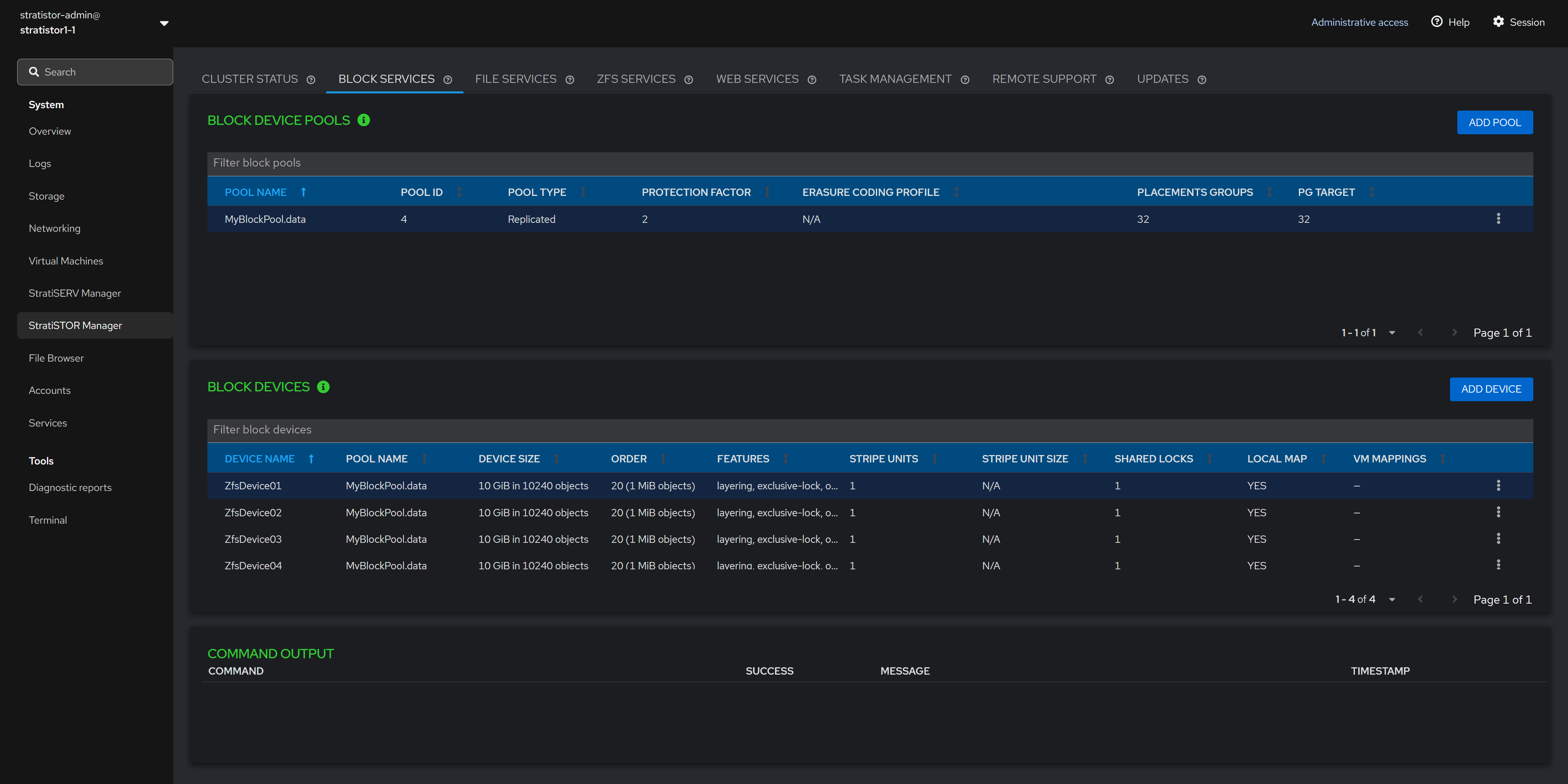
Once the cluster block devices are mapped to the host(s), they now appear as ZFS storage pool candidates within the Create ZFS Pool wizard (as StratiSTOR-backed block devices).
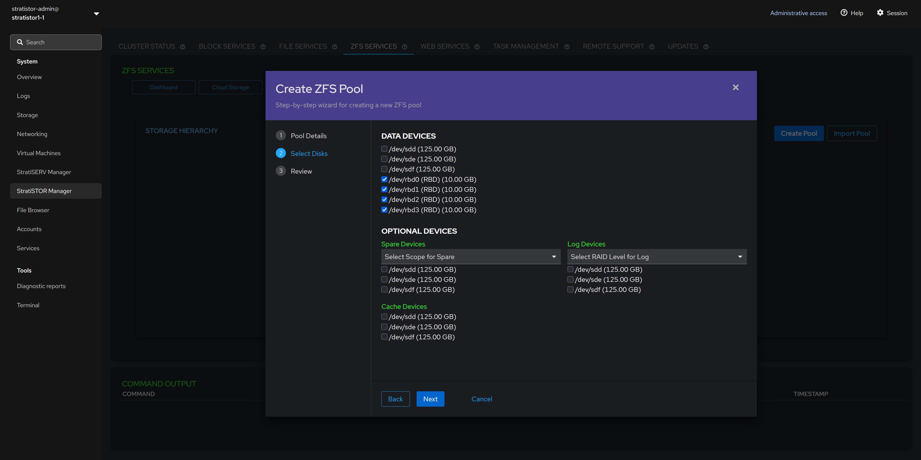
The rest of the ZFS pool creation wizard proceeds as it would with any block device.
¶ MANAGEMENT
¶ SDCACHE STAT TOOLS
There are two SDCache statistics tools used to evaluate SDCache effectiveness within the cluster.
¶ sdcache-stats
- PURPOSE: Displays device-level SDCache configuration and statistics values.
- USAGE:
/stratistor/config/sdcache/sdcache-stats.sh nvme0n1_sdcache - NOTES: Takes one input parameter for the SDCache device to poll. All SDCache disks are named [DISKNAME]_sdcache, e.g. nvme0n1_sdcache
- EXAMPLE OUTPUT:
[root@hyperserv01] /stratistor/config/sdcache/sdcache-stats.sh nvme0n1_sdcache
DEVICE
========Device-mapper device: nvme0n1_sdcache
Origin size: 88017162928128 bytes
Discards: trueCACHE
========
Cache Size: 17179869184 bytes
Cache Usage: 17179869184 bytes
Cache Usage: 100 %
Cache Read Hit: 1372494
Cache Read Miss: 1902572
Cache Write Hit: 4961268
Cache Write Miss: 1166941
Cache Dirty: 0 bytes
Cache Block Size: 8388608 bytes
Cache Promotions: 197067
Cache Demotions: 195019
Cache Migration Threshold: 8388608 bytes
Cache RW mode: rw
Cache Type: writethrough
Cache Policy: smq
Cache Status: OKMETADATA
========
Metadata Size: 134217728 bytes
Metadata Usage: 360448 bytes
Metadata Usage: 0 %
¶ sdcache-stats-summary
- PURPOSE: Displays node-level SDCache device statistics.
- USAGE:
/stratistor/config/sdcache/sdcache-stats-summary.sh - NOTES: Does not take any input parameters.
- EXAMPLE OUTPUT:
[root@hyperserv01] /stratistor/config/sdcache/sdcache-stats-summary.sh
nvme0n1_sdcache Size: 2048 MiBs Used: 100% Dirty: 0 MiBs RdHits: 1372505 RdMisses: 1902573 WrHits: 4961642 WrMisses: 1166948
nvme1n1_sdcache Size: 2048 MiBs Used: 100% Dirty: 0 MiBs RdHits: 1410233 RdMisses: 2120092 WrHits: 4314515 WrMisses: 1033996
nvme2n1_sdcache Size: 2048 MiBs Used: 100% Dirty: 0 MiBs RdHits: 1351561 RdMisses: 1620987 WrHits: 4791391 WrMisses: 1094991
nvme3n1_sdcache Size: 2048 MiBs Used: 100% Dirty: 0 MiBs RdHits: 1305210 RdMisses: 1760175 WrHits: 5006003 WrMisses: 1018588
nvme4n1_sdcache Size: 2048 MiBs Used: 97% Dirty: 0 MiBs RdHits: 1188546 RdMisses: 1827740 WrHits: 4180324 WrMisses: 1042968
nvme5n1_sdcache Size: 2048 MiBs Used: 99% Dirty: 0 MiBs RdHits: 1376959 RdMisses: 2300476 WrHits: 5418769 WrMisses: 1149760
nvme6n1_sdcache Size: 2048 MiBs Used: 99% Dirty: 0 MiBs RdHits: 1274088 RdMisses: 1961035 WrHits: 4311210 WrMisses: 1019593
nvme7n1_sdcache Size: 2048 MiBs Used: 100% Dirty: 0 MiBs RdHits: 1308130 RdMisses: 1778769 WrHits: 5143562 WrMisses: 907177
nvme8n1_sdcache Size: 2048 MiBs Used: 100% Dirty: 0 MiBs RdHits: 1358118 RdMisses: 1929373 WrHits: 4722214 WrMisses: 1031545
nvme9n1_sdcache Size: 2048 MiBs Used: 99% Dirty: 0 MiBs RdHits: 1303755 RdMisses: 1966529 WrHits: 4476744 WrMisses: 994870
¶ STRATISYSTEM SECURITY — HOST, STORAGE AND WORKLOAD PROTECTION
StratiSYSTEM integrates security across the infrastructure operating system, StratiSTOR storage services, StratiSERV compute and browser-delivered workspaces, and inter-site communication. These controls address separate security boundaries: administrative reachability, boot integrity, data at rest, VM memory, routed network traffic and remote user sessions. No single feature substitutes for access controls, key management or protection of the remaining data paths.
Control | Protected boundary | Key technical behavior |
Hardening Mode |
Host management interfaces |
Source-based IPv4/IPv6 trust ranges, persistent firewall configuration and safeguards against management lockout. |
Encrypted OS + Secure Boot |
Offline system volumes and startup trust |
At-rest protection of configured OS volumes and signature verification of boot components. |
StratiSTOR device encryption |
Storage media |
Encryption below block, file and object services for provisioned data, metadata and journal devices. |
Confidential computing |
Eligible guest memory |
Hardware-assisted protection of virtual-machine memory on compatible AMD or Intel platforms. |
Secure browser workspaces |
User application sessions |
Remote execution and configurable restrictions on clipboard, file transfers, printing and session duration. |
¶ Hardening Mode and Administrative Network Boundaries
Hardening Mode limits host-management access to explicitly trusted IPv4 or IPv6 addresses and CIDR ranges. Operators can define separate approved public and private management source ranges while preserving the connectivity required by storage, workload and infrastructure services. This creates a host-enforced boundary between administrative access and application/client networks, even when both can reach a common network segment.
The hardening workflow validates source definitions, persists firewall state and preserves the active management session while new rules are applied. Rollback safeguards help avoid accidental lockout caused by an incorrect trusted range or incomplete management path. A hardening change should still be validated from each intended operator network and across node restart and failover.
¶ Encrypted Operating System Volumes and Secure Boot
Operating-system volume encryption protects the contents of configured host volumes when the storage media is powered off or removed, including installed software, configuration and other locally retained information. Secure Boot addresses a different threat by verifying signed startup components against the platform trust chain before they execute. The two controls complement one another but are not interchangeable.
Once an encrypted volume is unlocked and mounted, normal file permissions, service credentials and authorization determine who may access it. Key-unlock, recovery and signing-trust procedures must support the intended operational model, particularly unattended recovery, hardware servicing and replacement of a failed node.
¶ StratiSTOR Storage-Device Encryption
StratiSTOR can encrypt selected storage devices at the device layer beneath its block, file and object interfaces. Applications continue using their usual storage protocols and data formats because encryption is applied below the client-visible service. The provisioned encryption boundary must include every device that stores protected data, metadata and journals; a partially encrypted storage layout cannot be described as fully encrypted at rest.
The confidentiality of removed or retired storage media depends on effective protection of unlock keys and recovery credentials. Device encryption does not replace application authorization, filesystem permissions or encrypted communication across the network.
¶ FIPS 140 Mode and Validation Scope
StratiSYSTEM provides FIPS mode support for approved-algorithm behavior and cryptographic self-tests in configured services. A formal FIPS 140 compliance statement is limited to the specific validated cryptographic modules, their approved modes of operation and the supported execution environments identified by applicable validation certificates. Enabling FIPS mode on a host does not, by itself, certify all StratiSYSTEM services or the complete infrastructure platform.
COMPLIANCE BOUNDARY: Document validated module versions, operating modes, applicable certificates and the services that use those modules. Assess gateway and application cryptography separately when a regulated deployment requires demonstrable FIPS 140 coverage.
¶ StratiSERV Confidential Computing and VM Memory Encryption
On supported AMD and Intel processors, StratiSERV can enable hardware-assisted encryption of eligible VM memory. The precise protection and isolation guarantees depend on processor capabilities, platform firmware, hypervisor support and guest configuration. Only VMs running on compatible, correctly configured hosts inherit the supported memory-protection features.
VM placement, restart and live-migration plans must preserve the required processor and platform capabilities. Guest disks, network traffic and all shared I/O buffers are not automatically covered by confidential-memory technology; those paths require their own corresponding encryption and access controls.
¶ StratiSERV Secure Browser and VDI Session Controls
StratiSERV can deliver remotely executed desktops, applications and isolated browsing sessions through a web browser. The user interacts with the hosted session while applications and working data remain within centrally managed infrastructure. The session boundary can be configured to restrict the direction of clipboard operations, downloads, uploads, printing and session duration.
Persistent profiles, mapped storage and permitted transfers continue to follow the configured data-access and authorization model. Browser delivery reduces the need to execute remote applications directly on the endpoint but does not replace identity validation, workload permissions or control of the hosted environment.
SECURITY OPERATIONS: Verify administrative trust ranges, volume unlock and recovery keys, device encryption coverage, eligible confidential-computing hosts, and browser-session restrictions as part of normal maintenance and failover validation.
¶ NETWORKING AND HARDWARE-AWARE PERFORMANCE
High-throughput StratiSTOR, StratiSERV, HyperSERV, SMB, NFS, OpenStack, AI, and Lustre workloads should be validated across the complete data path. Bonding, application multichannel, and storage multipathing solve different problems and should not be treated as interchangeable.
- Record each physical port, negotiated speed, NUMA node, IP address, route, MTU, bridge/bond membership, and workload role.
- Use persistent NetworkManager profiles for production configuration. Avoid relying on temporary
ipcommands for settings that must survive reboot. - For multiple 100 GbE or faster adapters, verify that traffic is actually distributed across the intended physical interfaces and that CPU/interrupt placement is not the bottleneck.
- Keep MTU consistent end-to-end for any network that uses jumbo frames.
ip -br link
ip -br addr
ip route show table all
nmcli device status
nmcli connection show --active
ethtool <interface>
ip -s link show <interface>
numactl -H 2>/dev/null || true
cat /proc/interrupts | head -80¶ UPDATES, MAINTENANCE, AND OFFLINE OPERATION
Use the release-specific StratiSYSTEM OS maintenance sequence for updates. An update can affect the management layer, host operating system, StratiSTOR services, StratiSERV services, Kubernetes, OpenStack, drivers, or firmware dependencies; do not assume every update has the same restart or reboot behavior.
- Record the installed version and enabled services before starting.
- Verify StratiSTOR protection state, StratiSERV workload placement, Kubernetes health, and destination capacity before maintenance.
- Use one-node-at-a-time maintenance when required by the release procedure and do not advance while the environment is degraded beyond the supported maintenance state.
- For offline environments, stage the approved repositories, packages, container images, and other release artifacts before the maintenance window and verify their integrity.
- After maintenance, validate software versions, cluster membership, data-service health, workloads, network persistence, and scheduled jobs.
¶ INCIDENT DIAGNOSTICS AND RECOVERY
When operationally practical, collect diagnostic evidence before rebooting a node or restarting a failed service. A reboot can clear the process state, pressure indicators, crash context, and transient kernel evidence needed to identify the root cause.
date -Is
hostnamectl
uname -a
uptime
free -h
vmstat 1 5
systemctl --failed --no-pager
dmesg -T | tail -300
journalctl -b -p warning --no-pager | tail -300
df -hT
lsblk -e7 -o NAME,PATH,SIZE,TYPE,FSTYPE,MOUNTPOINTS,MODEL,SERIAL
ip -s linkAlso capture the health/status output from every affected StratiSYSTEM service before recovery actions. For StratiSTOR, record service availability, data-protection state, capacity pressure, recovery activity, and device errors. For StratiSERV, record host state, VM state, migration restrictions, and resource pressure. If Kubernetes or OpenStack is enabled, capture pod, event, and service state for the affected namespace.
Temporary maintenance settings must be documented and returned to their intended operating state after recovery. Validate application access and data protection after the platform itself reports healthy.
¶ LOGGING
There are several logs which are used to track events within the StratiSYSTEM.
- STRATISTOR
- /var/log/messages
- General system log for all system-wide services and events
- /stratistor/logs/stratistor.log
- Log that captures only errors encountered with the provisioning engine.
- /stratistor/logs/cluster/
- Log that captures only cluster related events such as scheduled job results.
- /stratistor/logs/syncjobs
- Log that captures all events related to synchronization jobs activity.
- /stratistor/logs/upgrade
- Log that captures all events related to management layer upgrades.
- /var/log/messages
- STRATISERV
- /var/log/messages
- General system log for all system-wide services and events
- /stratiserv/logs/stratiserv.log
- Log that captures only errors encountered with the provisioning engine.
- /stratiserv/logs/cluster
- Log that captures only cluster related events such as scheduled job results.
- /stratiserv/logs/upgrade
- Log that captures all events related to management layer upgrades.
- /var/log/messages